On the way to a working Gameslab, I had a few failures, some more “fun” than others. For example, it turns out that when your giant Zynq FPGA heats up to 70C while idling without any configuration, you might have a problem somewhere. Also, don’t solder while batteries are plugged in. Things die when you do. And, let’s not forget my newly found, strong distaste for QFP parts.
Continue reading
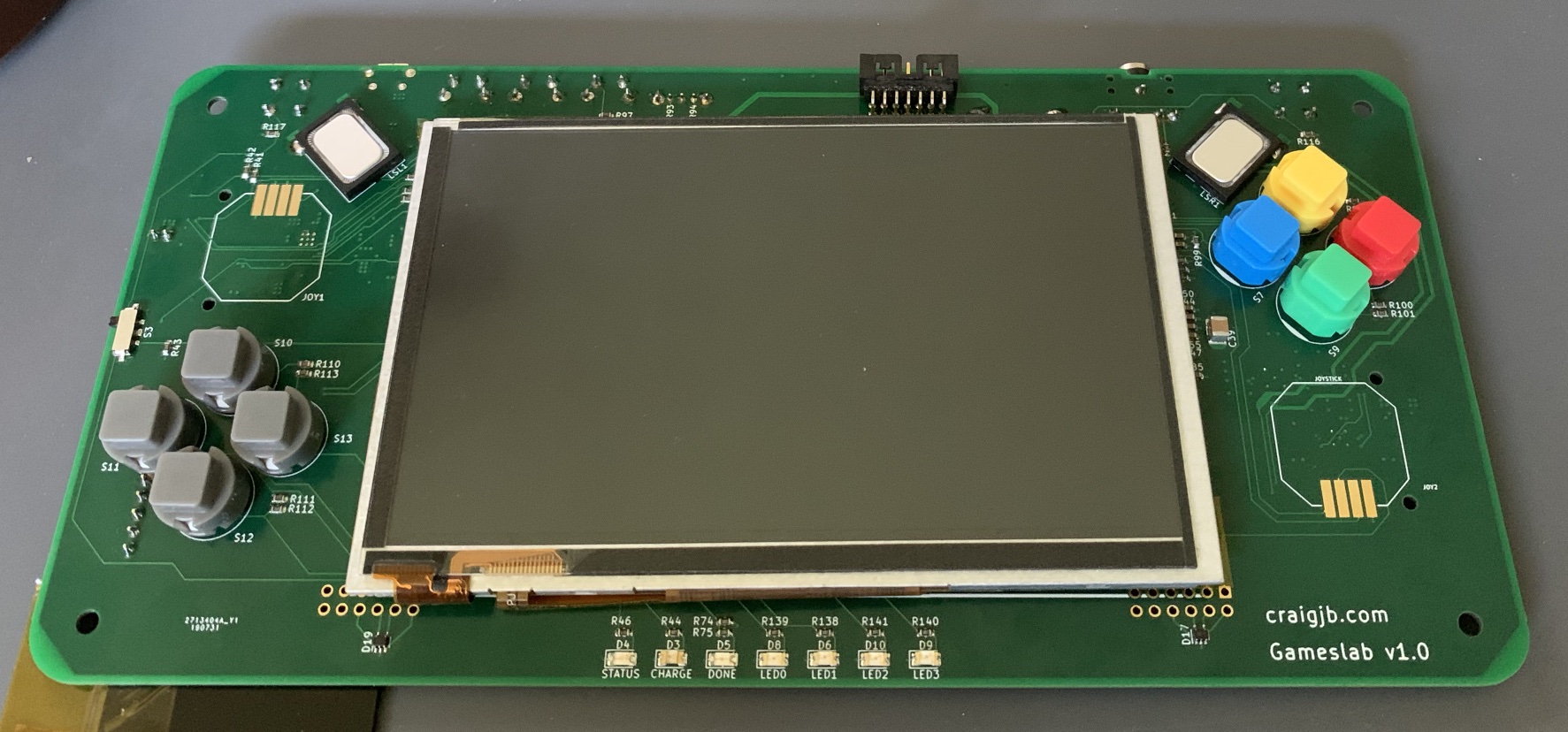
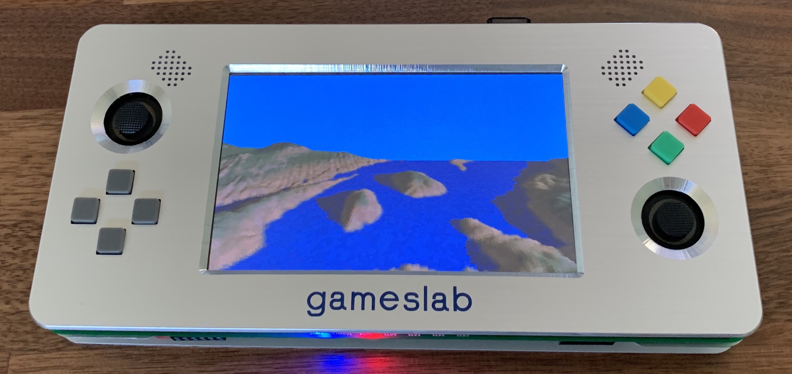
If you went to Hackaday Supercon 2019, you might have seen someone wandering around with a badge that was way too heavy looking. That was me! And that badge was a Gameslab, my FPGA-powered handheld game console. As the blog posts from years ago prove, I’ve been thinking about building Gameslab for a long time, and over the last few months, I have finally done it. In this post, I’ll explain what exactly a Gameslab is (game-slab, as in brick, or unwieldly object that plays games), why I built one, what’s in it, and how I got it working.
Continue reading
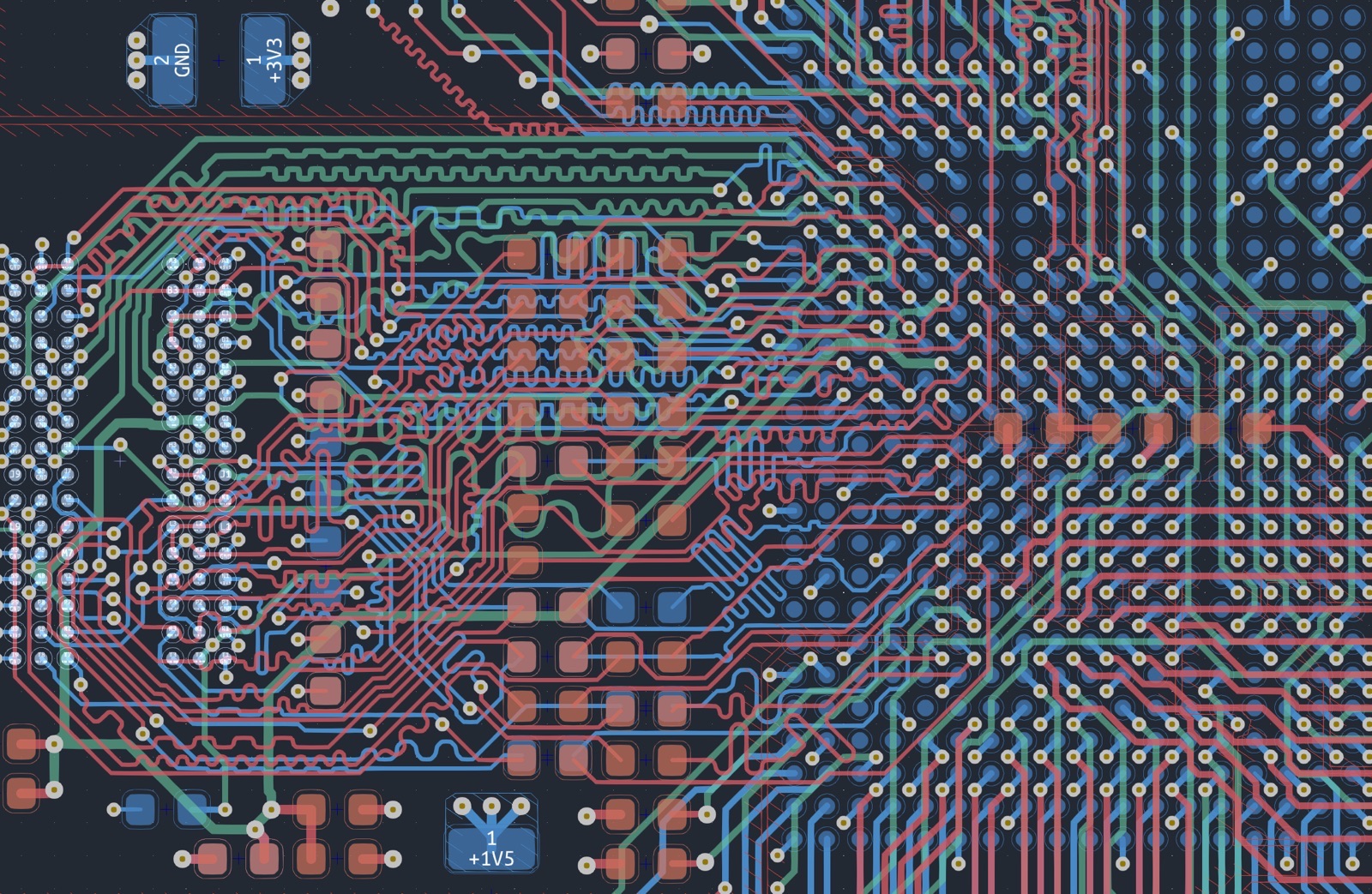
A few months ago, I bought a couple Xilinx Zynq XC7Z035s off of eBay. These are beefy parts, even today! Each one has a dual core ARM Cortex A9, DDR controller + other peripherals, and a giant FPGA fabric (275k “logic cells”). The description did say “refurbished”, and hopefully that means just reballed, which isn’t uncommon for these expensive parts. Anyway, since I bought them, I’ve been itching to design a board for the parts and try them out. Specifically, I’ve wanted to get around to designing and building my Gameslab portable game console project. Well, after years of thinking about it, I finally put in the time to design the boards. And, in this post plus a few more to come, I’ll write about that process in detail. Today, I want to talk about how to even start, since these high-speed parts have more requirements on the PCB than your typical microcontroller.
Continue reading
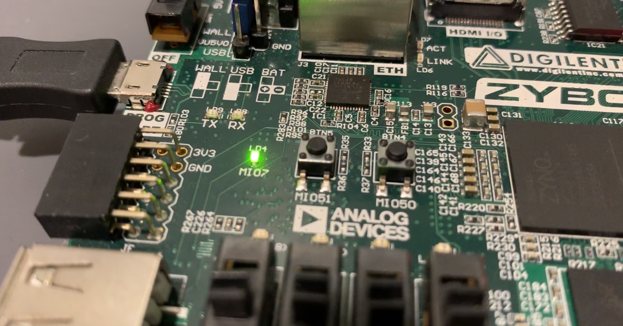
I recently scored a couple of XC7Z035s on Ebay from a chip seller in China! These are huge chips! The XC7Z010 on my Digilent Zybo dev-board has 28K logic cells and 240 KB of block RAM, while the XC7Z035 has 275K logic cells and 2 MB of block RAM (“logic cell” is a hazy term, but 275K is a lot!). So I’m excited to design a board for them, probably the forever-ongoing project, Gameslab. The prices to fab PCBs with 6 or even 8 layers keep dropping so fast, there isn’t an excuse now! JLCPCB even offers 6 layers with an impedance controlled stackup ($150 estimate for a 150x100mm board)! So, anyway, I’m excited to get back into FPGA stuff, so I’ve re-downloaded all the tools and set them up on a new virtual machine. To make sure I’ve got everything working, I thought a bare-metal blinking LED program would be a good place to start. This will ensure the cable drivers are installed, the ARM toolchain is setup, and that the JTAG download works. Essentially, I would use this same program to do the first test on a new board with a Zynq part.
Continue reading
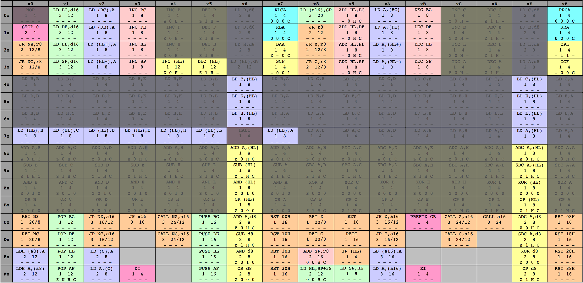
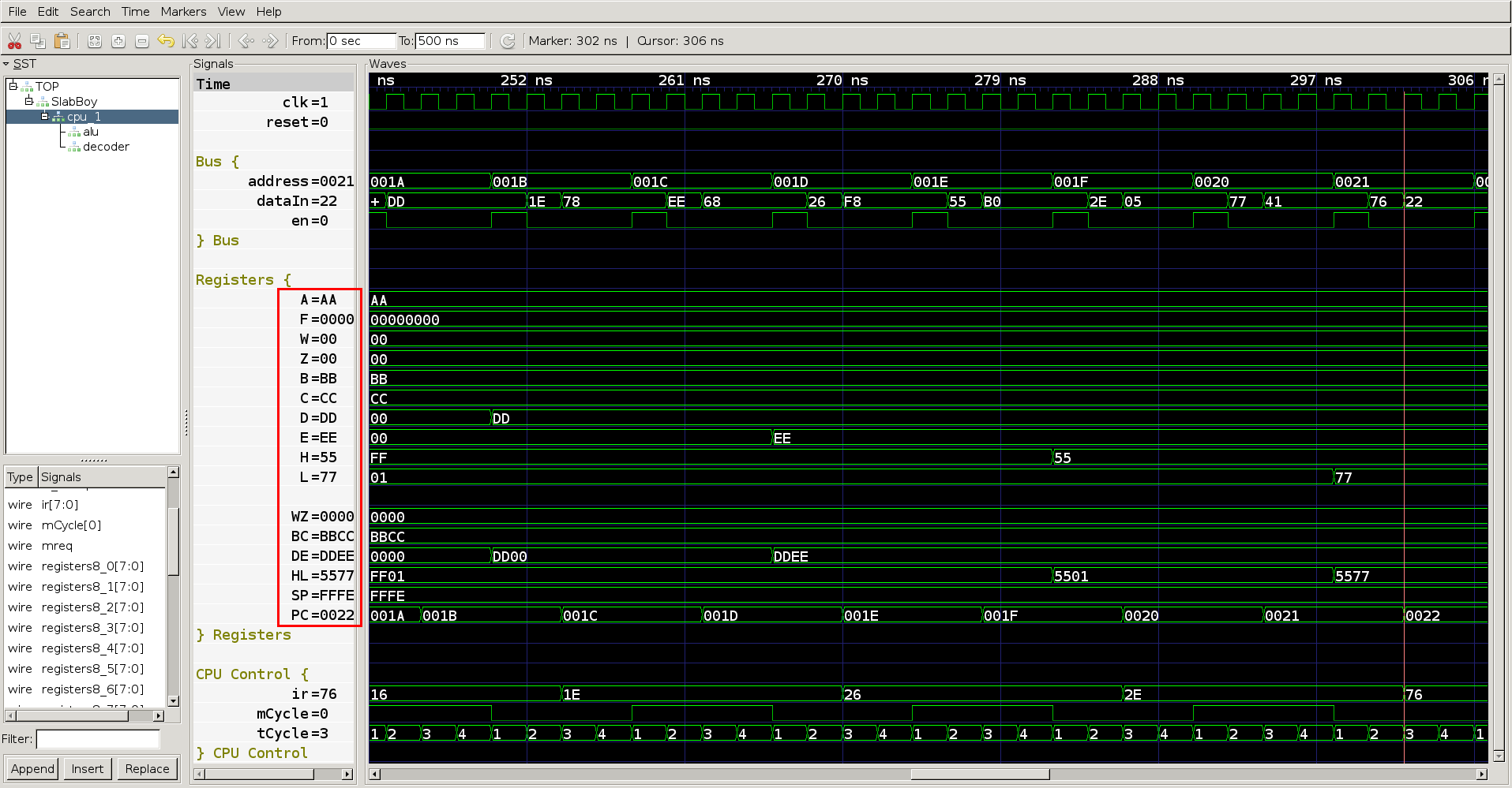
So far, the SlabBoy CPU can perform arithmetic operations and load 8-bit immediate values. Neither of these operations require accessing memory at an address other than the program counter (PC). In this post I’ll quickly implement the register-to-register load instructions, and then go on to implementing indirect addressing. Even though the indirect addressing will only support addressing by register HL for now, it fills gaps in the major 8-bit arithmetic and load instruction groups implemented so far. If you’re just starting reading about the Slab Boy here, I recommend reading this post since I skip a lot of the detailed commands and surrounding code here.
Continue reading
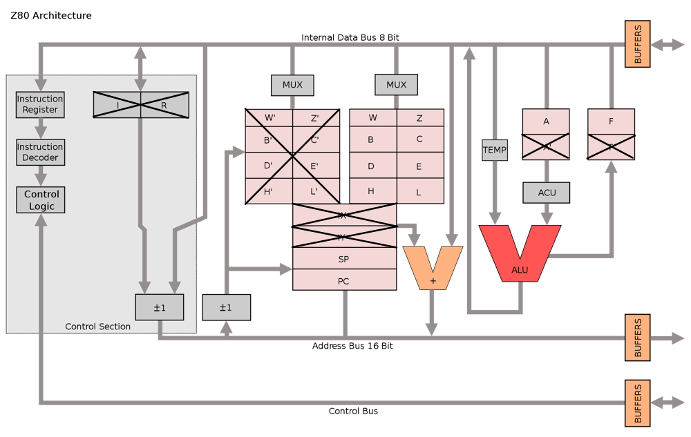
It’s been a little while, but in the last post I showed my SpinalHDL implementation of the Z80-ish ALU, part of the Game Boy’s LR35902 CPU. We could compile and run a program with NOP, INC, DEC, etc. However, because the microcode doesn’t support load instructions yet, building complex values is a bit difficult. In this post, I’m going to briefly show how I added the 8-bit LR35902 load-immediate instructions and the halt instruction to make simulating the CPU more friendly.
Continue reading
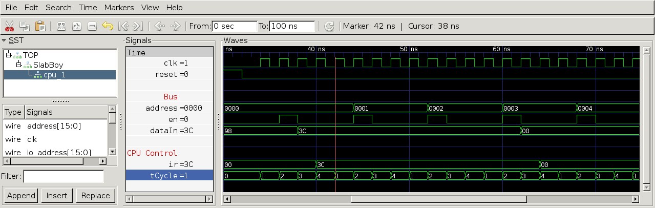
In the last post, I showed the test bench that loads an assembled Game Boy binary program, and we looked at the waveform output showing that the instruction fetch cycle worked. However, the instruction itself didn’t do anything. This time, I’m going to work on implementing the basic register-to-register arithmetic instructions, which are some of the simplest out of the whole instruction set. First, the CPU needs an ALU before it can execute arithmetic instructions. Then, it needs an instruction decoder to turn the op codes into the right control signals.
Continue reading
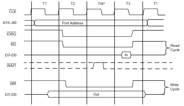
In the last post, I started talking about the internal cycles of the LR35902 CPU. In this post, I’d like to start implementing some instructions. Building a CPU RTL description is a large task, so it’d be crazy to try to implement everything all at once. Instead, I’m thinking of starting with the easy arithmetic instructions and then iterating from there. To make testing quick, I want to use an existing Game Boy assembler, feed the output binary into the test bench’s program memory somehow, and then run that program in the simulator. So first, I’m going to setup a new SpinalHDL project and build the basic instruction fetch state machine. Next, I’ll setup a test bench to visualize what’s happening. Finally, I’ll use the RGBDS assembler to create a program binary and load it into the test bench.
Continue reading
For a long time now, I’ve wanted to build some hardware emulators of older game consoles on an FPGA. In fact, that was one of the reasons I started designing a handheld game console, the Gameslab, based on the Xilinx Zynq FPGA+ARM combo. Eventually, I envision the Gameslab ARM CPU running an OS that allows you to pick a game, and each game can include custom hardware that is also loaded with the software. For example, one game could run on the ARM CPUs and include some custom graphics hardware on the FPGA fabric for fast rendering of terrain. Or, like the case I want to work on today, the game could load a whole game system into the FPGA fabric. Of course, there will be some trickery involved, and I’ve already started poking around some things, like Linux device tree overlays. However, today I want to start working on something more fun, a HW Game Boy emulator in the FPGA fabric, called the SlabBoy :)
Continue reading
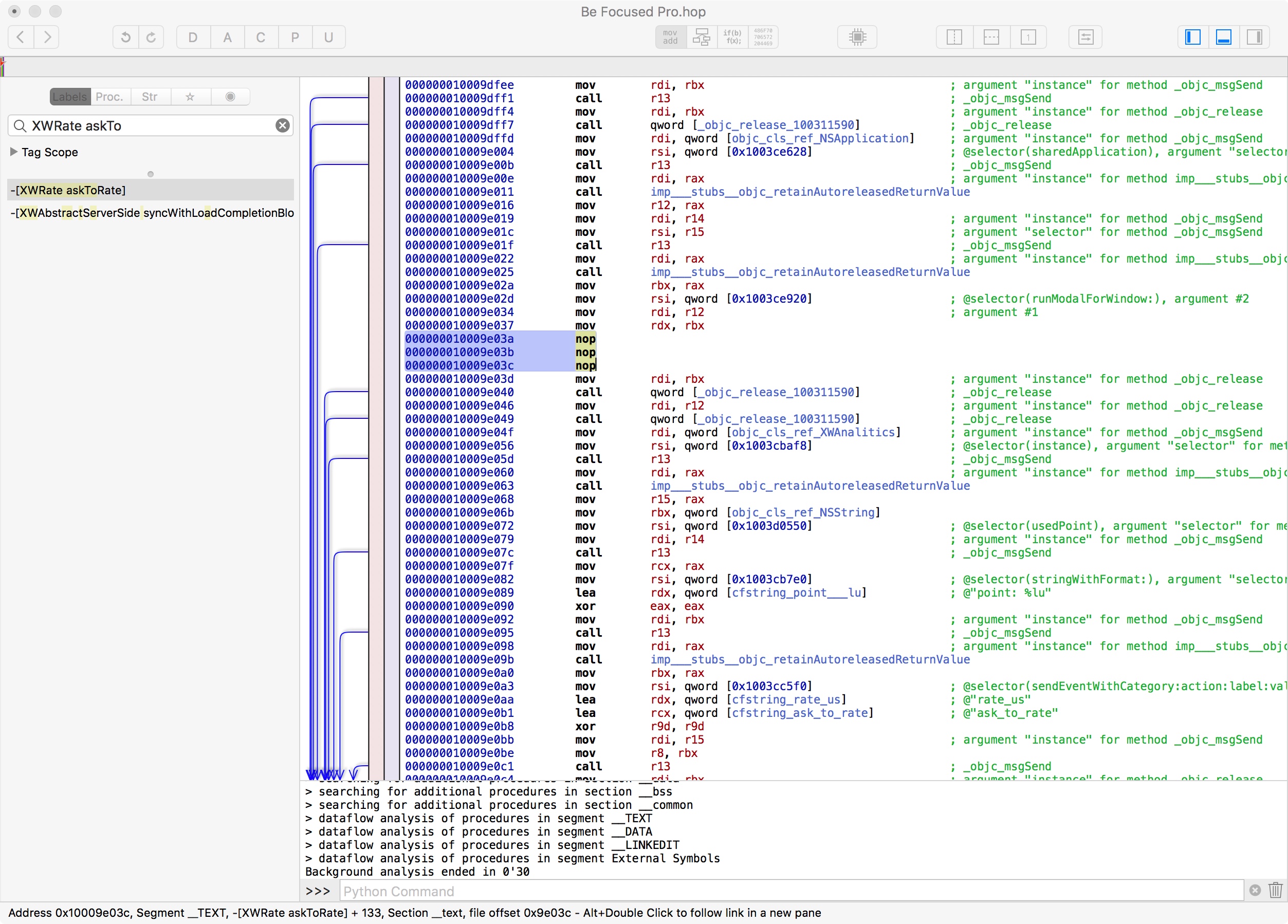
I recently started using an app called Be Focused Pro for focusing using the Pomodoro technique to focus a bit better. The free version of the app has ads and some pop-ups, so I paid $5 for the pro version to remove the ads. Afterward, I was unhappy to discover the app still persisted in annoying its pro users. Periodically, when you enter a 5-minute break, the app triggers a pop-up notification asking to rate the app in the AppStore. While normally I would just find another app, I actually really like this one’s user interface (and I already paid $5 for it). So instead, I decided to hack away the annoying pop-up and have the app I want.
Continue reading