FPGA Game Boy Part 5: Direct & indirect load instructions
So far, the SlabBoy CPU can perform arithmetic operations and load 8-bit immediate values. Neither of these operations require accessing memory at an address other than the program counter (PC). In this post I’ll quickly implement the register-to-register load instructions, and then go on to implementing indirect addressing. Even though the indirect addressing will only support addressing by register HL for now, it fills gaps in the major 8-bit arithmetic and load instruction groups implemented so far. If you’re just starting reading about the Slab Boy here, I recommend reading this post since I skip a lot of the detailed commands and surrounding code here.
8-bit register-to-register loads
The big purple block of instructions from row 4x-7x on the LR35902 instruction set chart consists of 8-bit register-to-register loads and a few indirect loads. I implement the direct register-to-register loads first, since the CPU doesn’t have any indirect addressing capabilities quite yet. Since the op-codes are arranged by source register, it’s easy to create a helper function to generate the microcode in the decoder module:
// helper function for the regular op code pattern
// used for most of the 8-bit reg-to-reg LD instructions
def load8BitRegToReg(base: Int, dest: Int) = {
  Seq(
    (base + 0, Seq(fetchCycle(AluOp.Nop, Some(Reg8.B), Some(dest)))),
    (base + 1, Seq(fetchCycle(AluOp.Nop, Some(Reg8.C), Some(dest)))),
    (base + 2, Seq(fetchCycle(AluOp.Nop, Some(Reg8.D), Some(dest)))),
    (base + 3, Seq(fetchCycle(AluOp.Nop, Some(Reg8.E), Some(dest)))),
    (base + 4, Seq(fetchCycle(AluOp.Nop, Some(Reg8.H), Some(dest)))),
    (base + 5, Seq(fetchCycle(AluOp.Nop, Some(Reg8.L), Some(dest)))),
    // TODO indirect (hl)
    (base + 7, Seq(fetchCycle(AluOp.Nop, Some(Reg8.A), Some(dest))))
  )
}
And then, I add all the direct load instructions to the microcode table:
val Microcode = Seq(
  ...
  ) ++
  load8BitRegToReg(0x40, Reg8.B) ++
  load8BitRegToReg(0x48, Reg8.C) ++
  load8BitRegToReg(0x50, Reg8.D) ++
  load8BitRegToReg(0x58, Reg8.E) ++
  load8BitRegToReg(0x60, Reg8.H) ++
  load8BitRegToReg(0x68, Reg8.L) ++
  load8BitRegToReg(0x78, Reg8.A) ++

  ...
And to test the new instructions, I just add a few register-to-register loads to the test program, assemble, and simulate. The waveforms look good.
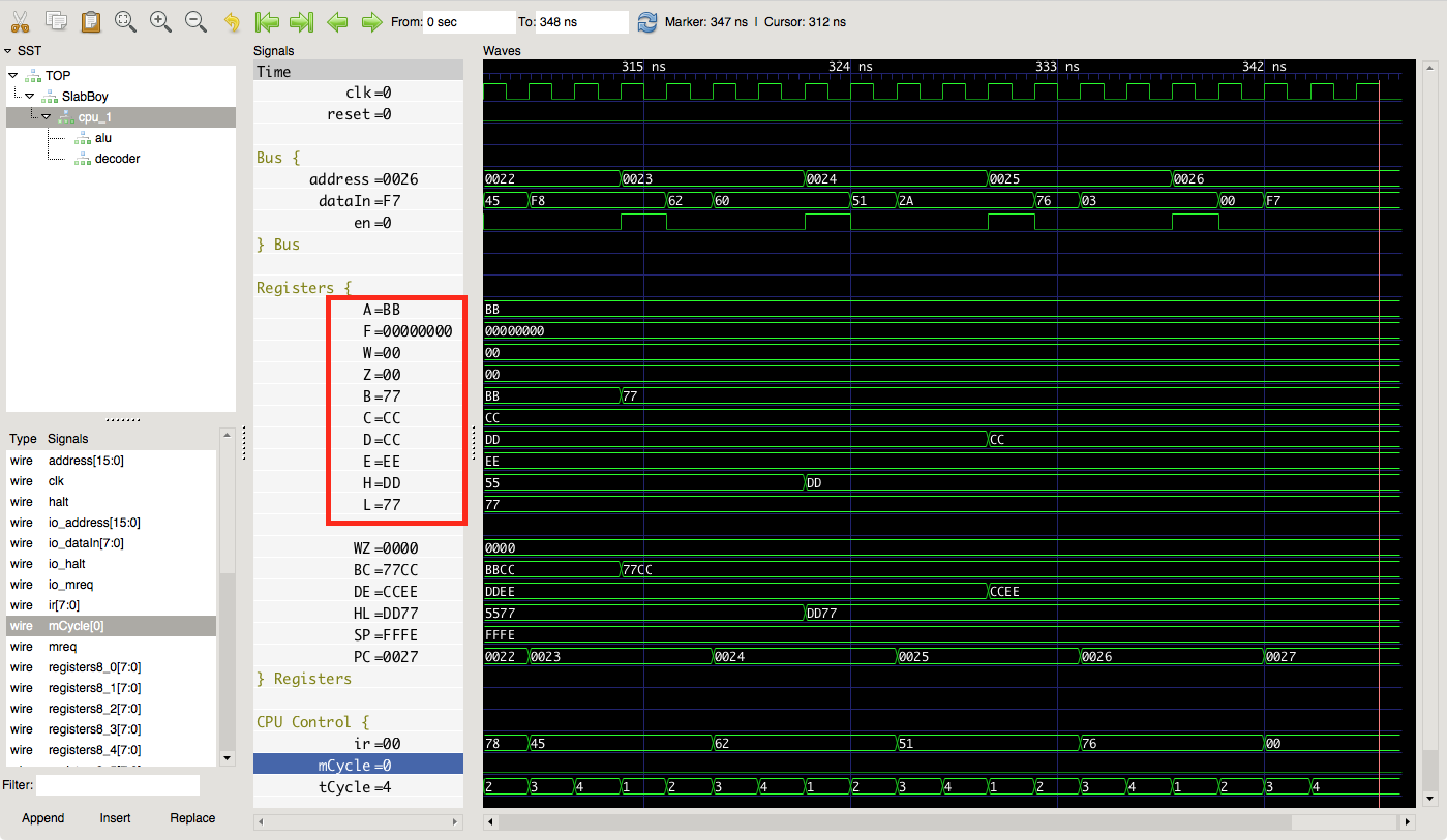 The register-to-register load instructions work—4 T-cycles each.
With the big block of load instructions out of the way, the SlabBoy now implements a good chunk of the non-prefixed LR35902 instructions. Looking at the chart, I think it’s time to implement indirect addressing to fill in the gaps.
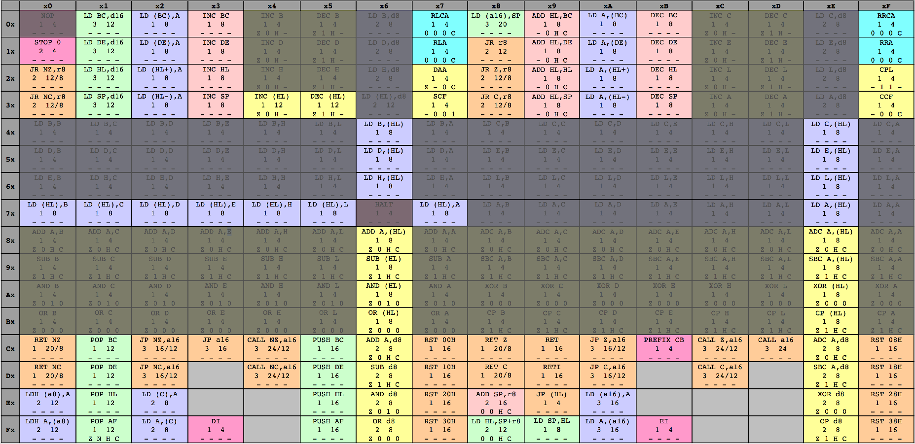 The unimplemented gaps in the 8-bit load and arithmetic instruction groups use indirect addressing.
Indirect addressing
Adding indirect addressing mostly means muxing the address load in t1State of the T-Cycle state machine. Since the fetch address is loaded in the on entry to t1State, the first M-cycle of the instruction must set the address source for the second M-cycle. Therefore, the decoder will output the next address source, and then the CPU state machine will register it for the rest of the M-cycle. This means the first fetch cycle will set the address source for the memory load cycle after it. And, it also means that the last cycle in each instruction will need to have PC as the next address source.
First, the CPU object needs a new enumeration for the possible address sources. We’ll start with just PC and HL, but there will be more.
object AddrSrc extends SpinalEnum {
  val PC, HL = newElement()
}
Then, the microcode needs a new field for the address source and some updates to the helper functions:
case class MCycle(
  aluOp: SpinalEnumElement[AluOp.type],
  opBSelect: Option[Int],
  storeSelect: Option[Int],
  memRead: Boolean,
  // sets the next M-cycle's address source
  nextAddrSrc: SpinalEnumElement[AddrSrc.type],
  halt: Boolean
)

def fetchCycle(aluOp: SpinalEnumElement[AluOp.type],
               opBSelect: Option[Int],
               storeSelect: Option[Int],
               nextAddrSrc: SpinalEnumElement[AddrSrc.type] = AddrSrc.PC) = {
  MCycle(aluOp, opBSelect, storeSelect, false, nextAddrSrc, false)
}

def memReadCycle(aluOp: SpinalEnumElement[AluOp.type],
                 storeSelect: Option[Int],
                 nextAddrSrc: SpinalEnumElement[AddrSrc.type] = AddrSrc.PC) = {
  MCycle(aluOp, None, storeSelect, true, nextAddrSrc, false)
}
Finally, in the CPU code we register the address source
val t1State: State = new State with EntryPoint {
  onEntry {
    // register address source from previous M-cycle
    addrSrc := decoder.io.nextAddrSrc
    // load address based on microcoded source
    switch(decoder.io.nextAddrSrc) {
      is(AddrSrc.PC) { address := registers16(Reg16.PC) }
      is(AddrSrc.HL) { address := registers16(Reg16.HL) }
    }

    mreq := True
  }
  whenIsActive {
    mreq := False
    goto(t2State)
  }
}
val t2State = new State {
  whenIsActive {
    when(decoder.io.memRead) {
      temp := io.dataIn
    }.otherwise {
      ir := io.dataIn
    }
    // only increment PC if PC was the address source
    // eventually this will be more complex to handle
    // auto-incremented indirect loads, etc
    when(addrSrc === AddrSrc.PC) {
      registers16(Reg16.PC) := registers16(Reg16.PC) + 1
    }
    goto(t3State)
  }
}
I add one instruction to the end of the microcode to give it a try, and add a few more instructions in the test program.
// ld A, [HL]
(0x7E, Seq(fetchCycle(AluOp.Nop, None, None, nextAddrSrc=AddrSrc.HL),
           memReadCycle(AluOp.Nop, Some(Reg8.A))))
ld h, $0
ld l, $4
ld a, [HL]
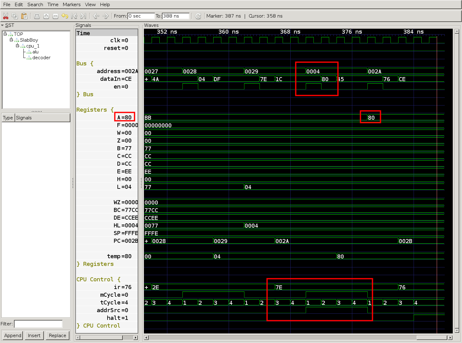 The fetch cycle sets the address source to HL, then the memory load cycle registers the source and uses address 0x0004 from register HL for the memory load.
Looks like the CPU loaded the value 0x80 from address 0x0004. Let’s just check real quick that address 0x0004 should have the value 0x80. I’ll just pop test.gb (the program binary) into vim in hex editor mode.
00000000: 3c04 0404 800c 0c91 910d 9125 ac3c 3c3c  <..........%.<<<
00000010: 3c2c b53e aa06 bb0e cc16 dd1e ee26 552e  <,.>.........&U.
00000020: 7778 4562 5126 002e 047e 7600 0000 0000  wxEbQ&...~v.....
00000030: 0000 0000 0000 0000 0000 0000 0000 0000  ................
Yup, address 0x0004 has value 0x80. Now it’s time to fan the microcode out to all the 8-bit load and arithmetic instructions. Since these instructions are already factored out into helper functions, it only takes a couple lines of new microcode.
// helper function for the regular op code pattern
// used for the bulk of the arithmetic instructions
def arithmetic8Bit(base: Int,
                   aluOp: SpinalEnumElement[AluOp.type]
                  ) : Seq[(Int, Seq[MCycle])] = {
  val store = if (aluOp == AluOp.Cp) { None } else { Some(Reg8.A) }
  Seq(
    (base + 0, Seq(fetchCycle(aluOp, Some(Reg8.B), store))),
    (base + 1, Seq(fetchCycle(aluOp, Some(Reg8.C), store))),
    (base + 2, Seq(fetchCycle(aluOp, Some(Reg8.D), store))),
    (base + 3, Seq(fetchCycle(aluOp, Some(Reg8.E), store))),
    (base + 4, Seq(fetchCycle(aluOp, Some(Reg8.H), store))),
    (base + 5, Seq(fetchCycle(aluOp, Some(Reg8.L), store))),
    // indirect arithmetic
    (base + 6, Seq(fetchCycle(AluOp.Nop, None, None, nextAddrSrc=AddrSrc.HL),
             memReadCycle(aluOp, store))),
    (base + 7, Seq(fetchCycle(aluOp, Some(Reg8.A), store)))
  )
}

// helper function for the regular op code pattern
// used for most of the 8-bit reg-to-reg LD instructions
def load8BitRegToReg(base: Int, dest: Int) = {
  Seq(
    (base + 0, Seq(fetchCycle(AluOp.Nop, Some(Reg8.B), Some(dest)))),
    (base + 1, Seq(fetchCycle(AluOp.Nop, Some(Reg8.C), Some(dest)))),
    (base + 2, Seq(fetchCycle(AluOp.Nop, Some(Reg8.D), Some(dest)))),
    (base + 3, Seq(fetchCycle(AluOp.Nop, Some(Reg8.E), Some(dest)))),
    (base + 4, Seq(fetchCycle(AluOp.Nop, Some(Reg8.H), Some(dest)))),
    (base + 5, Seq(fetchCycle(AluOp.Nop, Some(Reg8.L), Some(dest)))),
    // indirect load
    (base + 6, Seq(fetchCycle(AluOp.Nop, None, None, nextAddrSrc=AddrSrc.HL),
             memReadCycle(AluOp.Nop, Some(dest)))),
    (base + 7, Seq(fetchCycle(AluOp.Nop, Some(Reg8.A), Some(dest))))
  )
}
I’ll do some more extensive testing later, but for now I’ll add an indirect add instruction to the test program:
ld h, $0
ld l, $4
ld a, [HL]

ld h, $0
ld l, $3
add a, [HL]

halt
This program loads the value 0x80 from address 0x0004 and adds the value loaded from address 0x0003, which is 0x04. Therefore the value of the accumulator should be 0x84 at the end of the program. The result looks good in the waveform below.
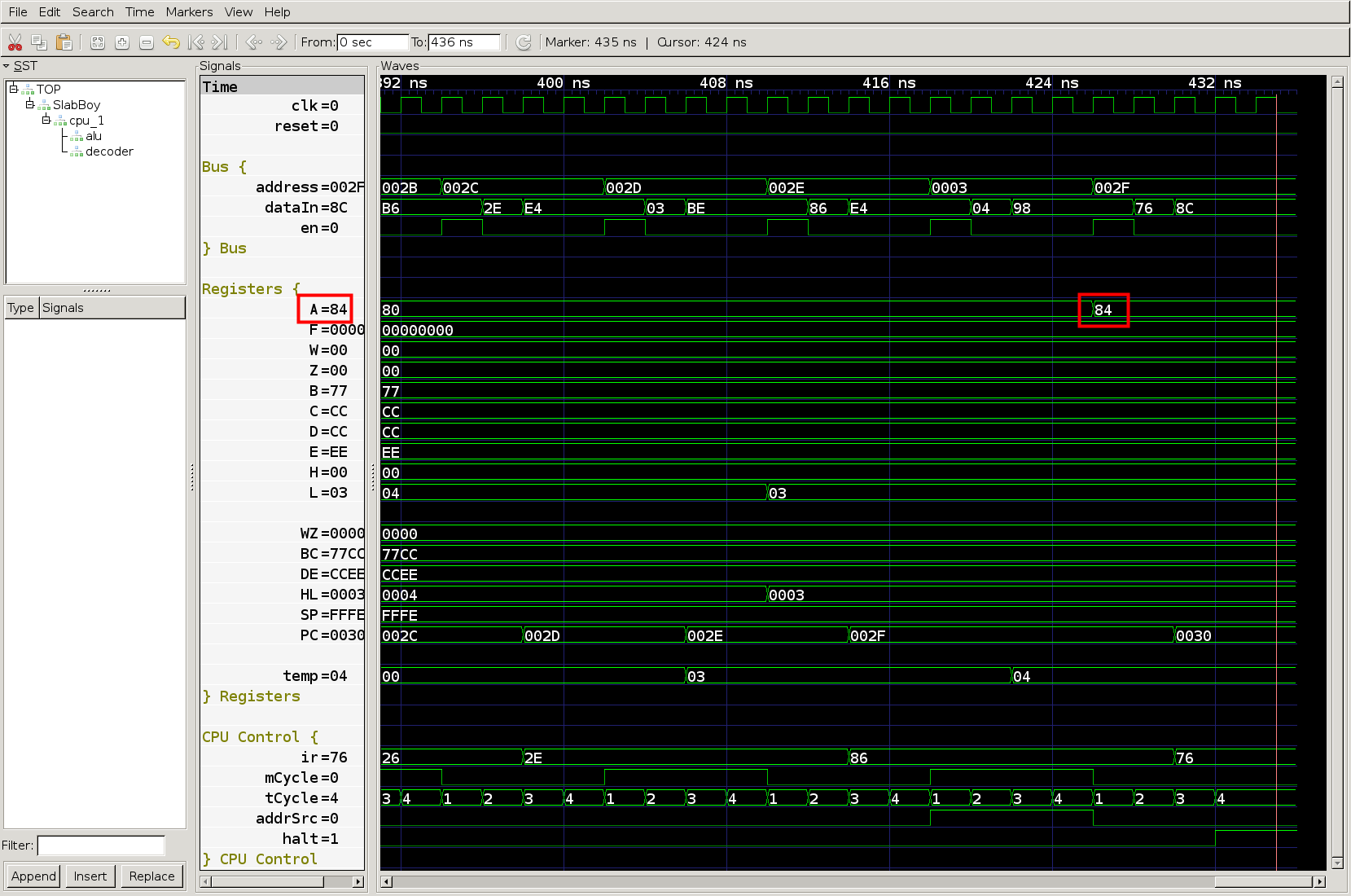 The accumulator first loads 0x80 from address 0x0004 and then adds 0x04 from address 0x003, resulting in 0x84.