
Atlys FPGA reset shenanigans
I’ve been playing around the last few days building a Microblaze processor system on the Digilent Atlys Spartan 6 board. I think my end goal is to boot Linux on it–but for now I’ll settle for booting Das U-Boot. It’s definitely been an interesting journey, since I decided against using the Xilinx-specific git repositories for everything, and instead I used mainline checkouts wherever possible. In another post I’ll go through the hell it took to compile a working GCC with Glibc for little-endian Microblaze. But, in this post I wanted to point out something a little more devious.
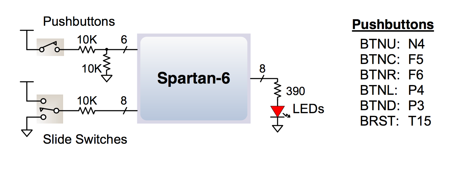
In the Atlys board reference manual, you might see something like this: “One pushbutton has a red plunger and is labeled “reset” on the PCB silkscreen this button is no different than the other five, but it can be used as a reset input to processor systems.” And below it is a diagram like this:
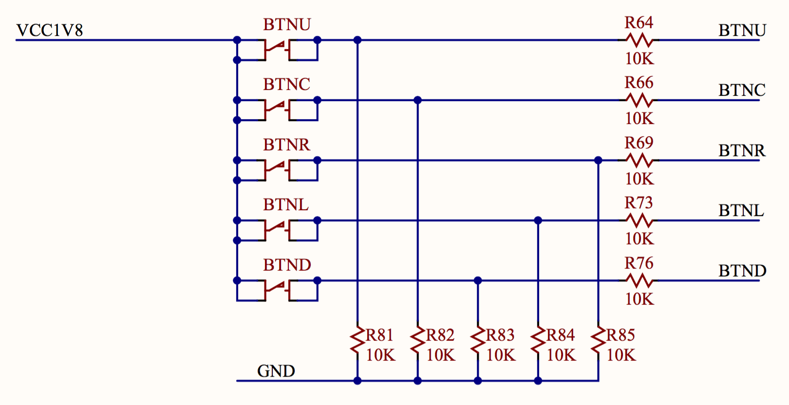
Well, both of these are lies. I spent so long trying to figure this out, a lot of it because the Xilinx system reset IP block will start running your code for a little while before the reset triggers and the system does nothing. On top of that, it’s not particularly deterministic, so I observed random behavior–not exactly conducive to debugging! After awhile, I knew the problem was with the reset circuit because the program would execute correctly if I held down the reset button. Also, it seemed odd that the processor did not reset itself after configuration, like it should have according to most sources I read. And the most damning evidence of all, the schematic! Here are the regular push-buttons:
And here is the reset button:
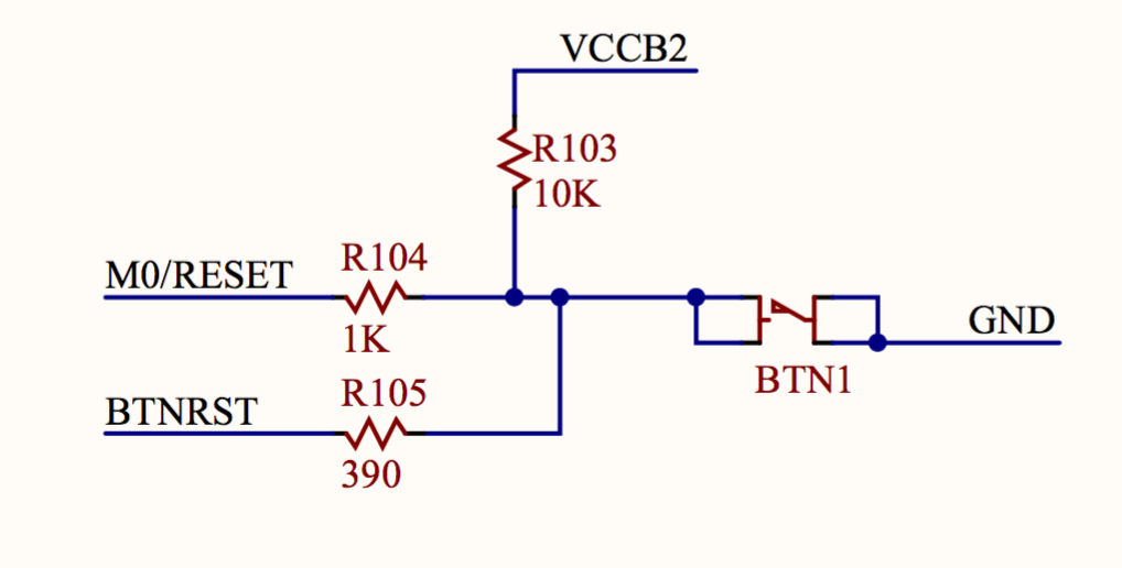 In case you are wondering, like I was, what the second reset button net is connected to, it goes to the Cypress USB chip for the Digilent programming interface.
That’s an active low reset! To fix the problem in the Xilinx XPS tool, flip the extern reset polarity on the proc_sys_reset block to “0”. And, you also have to flip the interrupt controller reset input polarity as well. Oh, and that will still give you a platform generator DRC error until you open the project .mhs file and change the external reset port RESET_POLARITY option to 0.
Now my system can send characters on the UART and correctly delay turning on some LEDs using simple delay loops. However, now I’m facing another fun problem: I can send data over the UART from the Microblaze, but so far I have been unable to receive data on the Microblaze. I’m using the Xilinx uartlite core, and the receive FIFO data valid bit in the status register never changes! I tried several different baud rates, checked all the .UCF constraints, and checked all the register addresses. Anyway, once I solve that problem, I can load a Das U-Boot image into the QSPI flash on the board, and hopefully start up the U-Boot console. Compiling U-Boot and configuring it is also a lot of fun, but I’ll write about that later.