Zynq Bare-Metal Blinky
I recently scored a couple of XC7Z035s on Ebay from a chip seller in China! These are huge chips! The XC7Z010 on my Digilent Zybo dev-board has 28K logic cells and 240 KB of block RAM, while the XC7Z035 has 275K logic cells and 2 MB of block RAM (“logic cell” is a hazy term, but 275K is a lot!). So I’m excited to design a board for them, probably the forever-ongoing project, Gameslab. The prices to fab PCBs with 6 or even 8 layers keep dropping so fast, there isn’t an excuse now! JLCPCB even offers 6 layers with an impedance controlled stackup ($150 estimate for a 150x100mm board)! So, anyway, I’m excited to get back into FPGA stuff, so I’ve re-downloaded all the tools and set them up on a new virtual machine. To make sure I’ve got everything working, I thought a bare-metal blinking LED program would be a good place to start. This will ensure the cable drivers are installed, the ARM toolchain is setup, and that the JTAG download works. Essentially, I would use this same program to do the first test on a new board with a Zynq part.
Set up
Since I don’t have a board designed and fabbed yet, I’m going to use the Digilent Zybo dev-board I have on my desk. This board has been incredibly handy, and I’ve even fabbed a couple of add-on boards to test different things. For running the bare-metal blinky program, make sure the boot mode jumper is in the “JTAG” setting. Otherwise, it will automatically start running whatever is in the QSPI flash or SD card. The board has all kinds of peripherals, DDR RAM, etc, but today I’m just going to use one LED connected to an MIO pin. The IO pins on the Zynq parts can be controlled by the ARM processor side or the FPGA side, and there are lots of ways to map the pins. The MIO pins are the easiest though, since these are directly mapped to the ARM GPIO peripheral.
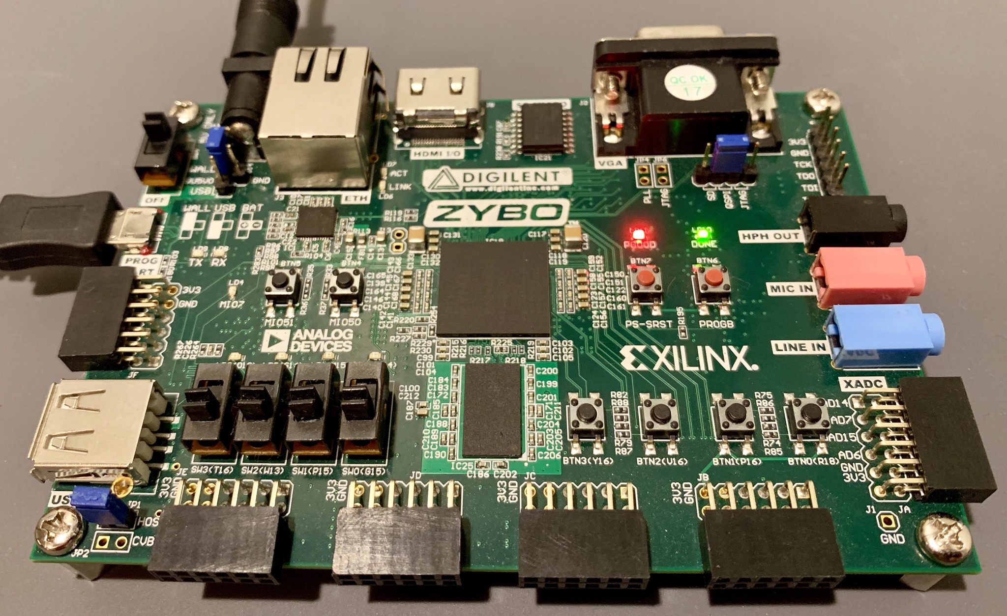 Digilent Zybo deb-board with power and USB programming+UART connected up
I’m really not a fan of using the heavy-weight Eclipse SDK software from Xilinx for development, especially since I want to run some minimal assembly code. So, a long time ago I found the magic shell script that sets up all the SDK paths. In a shell, run source <Xilinx install dir>/Xilinx/SDK/2018.3/settings64.sh (2018.3 is my installed version). Now, running arm-linux-gnueabihf-as --version should dump out version info. I use these tools for everything on my FPGA dev virtual machine, so I’ve added that source line to the end of my ~/.bashrc.
You can also use GCC and binutils from Linux distro packages. For example, Ubuntu has the packages: gcc-arm-linux-gnueabihf and binutils-arm-linux-gnueabihf.
The code
I don’t want to mess around with bootloaders or the Xilinx FSBL (first stage bootloader) or anything right now, so I’m going to write some super simple ARM assembly to blink an LED. Then, after assembling, the blinky program can be loaded over JTAG and run. The assembly program only needs a few simple parts: a vector table, some GPIO setup code, and a blinky loop.
ARM processors have a table of exception vectors, starting at the reset vector, which handle different events. For example, the first vector defines what to do when the chip starts up or is reset. Most of the time the reset vector branches to the real code, located after the vector table. Other vectors handle things like the CPU encountering an undefined instruction (which can happen if you branch into data memory, for example).
For this program, I want to branch to the blinky code, so only the reset vector points somewhere. The other vectors are endless loops. In blink.s I’ve started with this:
@@@@@@@@@@@@@@@@@@@@@@@@@@@@@@@@@@@@@@@
@ Vector table

.section .text
.code 32
.globl vectors
vectors:
    b entry         @ reset
    b .             @ undefined instruction
    b .             @ software interrupt
    b .             @ prefetch abort
    b .             @ data abort
    b .             @ hypervisor entry
    b .             @ interrupt
    b .             @ fast interrupt

entry:
    @ code here
Now to actually start writing the GPIO setup code, I had to read through the Zynq technical reference manual for a while. It looks like first the MIO pin has to be configured in the System Level Control Registers (SLCR) to set it’s IO type, speed, pullup, etc. But, first, to make any changes to the SLCR, they have to be unlocked. Unlocking requires writing a specific value to the SLCR_UNLOCK register. Then, after changes, the SLCR are locked by writing a specific to the SLCR_LOCK register. After setting the MIO pin modes, I set the GPIO pin direction to output and enable the output.
entry:
    @ unlock SLCR
    ldr r0, SLCR_BASE
    ldr r1, SLCR_UNLOCK_KEY
    str r1, [r0, #C_SLCR_UNLOCK]

    @ setup MIO pin, LVCMO33 and no tri-state
    mov r1, #0x600
    str r1, [r0, #C_SLCR_MIO_PIN_07]

    @ lock SLCR
    ldr r1, SLCR_LOCK_KEY
    str r1, [r0, #C_SLCR_LOCK]

    @ setup GPIO dir, output en, and data
    ldr r0, GPIO_BASE
    mov r1, #0x80
    mov r2, #0x0
    str r1, [r0, #C_GPIO_DIRM_0]
    str r1, [r0, #C_GPIO_OEN_0]
    str r1, [r0, #C_GPIO_DATA_0]
Above, I’m using some constants I defined, like SLCR_BASE. Where do these come from? Well, ARM assembly immediate values are pretty flexible, due to the free barrel-shift operation with all instructions, but not every value can be generated. So, typically ARM programs have a table of constants (or some people call them literals) which are loaded into registers when needed. In the snippet below, I first define my constant values using .equ which is the same as #define in C, and then I put my constants into the code memory in the literal table at the end. .word is an assembly directive to output the value in the resulting machine code binary. To use the constants later, I give them a label. Usually the constants are stored after the assembly program or subroutine, otherwise they’d be executed as code.
Above, you might also notice the instruction: str r1, [r0, #C_SLCR_UNLOCK]. The second operand uses offset addressing, which is quite common in assembly programs that interact with sets of registers. The base address for a peripheral can be loaded into one register, then all the registers can be accessed by their address offset from the base, instead of loading an address literal each time. Since most offset values are small, the ARM load immediate instruction can handle them, which means we don’t need to have all the offsets in a constant table.
@@@@@@@@@@@@@@@@@@@@@@@@@@@@@@@@@@@@@@@
@ Constants

.equ C_GPIO_BASE,       0xE000A000
.equ C_GPIO_DIRM_0,     0x00000204
.equ C_GPIO_OEN_0,      0x00000208
.equ C_GPIO_DATA_0,     0x00000040
.equ C_SLCR_BASE,       0xF8000000
.equ C_SLCR_UNLOCK,     0x00000008
.equ C_SLCR_LOCK,       0x00000004
.equ C_SLCR_MIO_PIN_07, 0x0000071C
.equ C_SLCR_LOCK_KEY,   0x767B
.equ C_SLCR_UNLOCK_KEY, 0xDF0D

.equ C_DELAY,           0x00400000

@ CODE HERE

@@@@@@@@@@@@@@@@@@@@@@@@@@@@@@@@@@@@@@@
@ Literal table
GPIO_BASE:       .word C_GPIO_BASE
SLCR_BASE:       .word C_SLCR_BASE
SLCR_LOCK_KEY:   .word C_SLCR_LOCK_KEY
SLCR_UNLOCK_KEY: .word C_SLCR_UNLOCK_KEY
Finally, the only component missing is the blinky loop. This code loads a constant delay value into a register, and subtracts one in a loop. Once the counter hits zero, the GPIO pin is turned on or off and the counter is reloaded. Of course the actual delay depends on the clock frequency, but this simple code will at least blink.
loop_outer:
    mov r3, #C_DELAY
loop0:
    SUBS r3, r3, #1
    BNE loop0

    str r2, [r0, #C_GPIO_DATA_0]

    mov r3, #C_DELAY
loop1:
    SUBS r3, r3, #1
    BNE loop1

    str r1, [r0, #C_GPIO_DATA_0]
    b loop_outer


    b .  @ just in case
Assembling and linking
I’m a big fan of automating builds, even for simple things like this. Often times, I come back months or even years later and have no idea how to use a toolchain or build a project. But, if I have a Makefile, I know how to use that and can figure it out from there. This is especially helpful for the weird Xilinx command line tools that don’t follow standard command-line interface conventions.
all:
    arm-linux-gnueabihf-as -o blink.o blink.s
    arm-linux-gnueabihf-ld -o blink.elf -T blink.ld blink.o

run:
    xsct blink.tcl
The Makefile for assembling the blinky program calls arm-linux-gnueabihf-as to go from assembly to a machine code .obj file. The call to arm-linux-gnueabihf-ld links the compiled .obj file using the supplied linker script blink.ld. Since this is an embedded target, the memory layout is not known by the compiler, so it’s specified by the linker script. In this case, the script simply says put all the code in memory starting at address 0 (.section .text in the assembly above corresponds to the .text section in the linker script).
SECTIONS {
    . = 0x0;
    .text : { *(.text) }
}
Running
Finally, the program is ready to run on the hardware. There are tons of ways to do this, but I’m going to use the built-in Digilent JTAG on the Zybo board (this requires the Digilent cable drivers to be installed for Vivado). Also, I again don’t want to use the Xilinx GUI tools for such a simple task since they can’t be automated in a Makefile. So, I’m going to use XSCT (Xilinx Software Command-Line Tool), which can connect over JTAG and upload the program. XSCT can be run in interactive mode, which is handy for checking if the JTAG target is connected, but I’m going to create a script to run it in batch mode. XSCT is basically a TCL REPL with Xilinx functions loaded in the environment for you, and it supports specifying a TCL script to run in that environment. So, I created the minimal TCL script to upload blink.elf to the target:
connect
targets -set -nocase -filter {name =~ "ARM* #0"}
rst -system
dow blink.elf
con
The XSCT targets command conveniently lets you use a wildcard in the name to find the right device. rst -system does a CPU reset and halt. dow blink.elf downloads the blink program into the memory at the address specified in the .elf file (from the linker script). Finally, the con command continues execution, which, since the CPU was just reset, starts at address 0.
And… it’s alive!