
Rust on Risc-V (VexRiscv) on SpinalHDL with SymbiFlow on the Hackaday Supercon Badge
What do Rust, Risc-V, and SpinalHDL all have in common? They can all run on the Hackaday Supercon 2019 badge! In this rather lengthy post, I go through how to get started with SpinalHDL on the badge, how to setup a Risc-V soft core using VexRiscv, how to assemble a basic program for it, and finally how to target and build embedded Rust for it.
What is SpinalHDL
SpinalHDL is one of what seems like many new up-and-coming hardware description languages (HDLs) that aim to simplify digital design and remove the tedium of Verilog or VHDL. I happen to really like SpinalHDL for its static typing, the underlying expressiveness of the Scala language, the already large SpinalHDL standard library, and the amazing responsiveness of SpinalHDL’s creator, Charles Papon. If you aren’t quite sure what a hardware description language is, or what an FPGA does, check out this awesome introduction from Hackaday Supercon).
Unlike Verilog, SpinalHDL makes it clear that you are writing a program that generates hardware; or put another way, programmatically constructing a description of hardware. The expressiveness of this model combined with Scala (SpinalHDL is built on top of Scala as a DSL) allows you to create much higher-level abstractions. For example, the VexRiscv CPU project is built on SpinalHDL, and is completely configurable from a bare-bones minimal CPU to a full-fledge Linux capable processor with MMU, caches, and more (the popular LiteX platform uses VexRiscv). All of this configuration is done using a plugin system, and you can even add your own custom instructions to the CPU by creating a plugin, which is very different from mucking around in the middle of a Verilog behemoth.
One of my favorite features is the library that comes with SpinalHDL. It includes a variety of standard bus definitions, decoders, crossbars (for example, an AXI4 crossbar generator), and more. These have saved me hours. For example, creating a 2-bit read-write register on an APB bus is as simple as this:
Apb3SlaveFactory(io.apb).createReadWrite(Bits(2 bits), 0x10000000L, 0)
If you would like a bit more introduction, here’s a conference talk from Charles introducing the SpinalHDL paradigm.
If you ever run into a problem in SpinalHDL that you can’t figure out, head over to the Gitter chat. It can be frustrating using up-and-coming tools when Google searches don’t turn up any solutions. Luckily, the SpinalHDL community is very helpful, and Charles (Dolu1990 on Gitter) has helped me a bunch.
Also, you may want to bookmark the SpinalHDL documentation.
Getting started with SpinalHDL
To get started actually using SpinalHDL, we’re going to need to install a few prerequisites:
-
Install a JDK
- On Ubuntu:
sudo apt-get install openjdk-8-jdk - On macOS:
brew cask install java
- On Ubuntu:
-
Install sbt (Scala build tool)
- On Ubuntu
Instructions from here
echo "deb https://dl.bintray.com/sbt/debian /" | sudo tee -a /etc/apt/sources.list.d/sbt.list curl -sL "https://keyserver.ubuntu.com/pks/lookup?op=get&search=0x2EE0EA64E40A89B84B2DF73499E82A75642AC823" | sudo apt-key add sudo apt-get update sudo apt-get install sbt - On macOS:
brew install sbt
- On Ubuntu
Instructions from here
Now we can actually create our project directory and get to work. I created a blinky directory and opened build.sbt in my editor. SpinalHDL (and Scala) projects use build.sbt to specify project metadata, dependencies, versioning, etc. It’s very similar to Cargo.toml in the Rust ecosystem. I created a minimal SpinalHDL build.sbt for this blinky project.
name := "riscv-blinky"

version := "0.1.0"

scalaVersion := "2.11.12"

libraryDependencies ++= Seq(
  "com.github.spinalhdl" % "spinalhdl-core_2.11" % "latest.release",
  "com.github.spinalhdl" % "spinalhdl-lib_2.11" % "latest.release"
)

fork := true
Most of the options are straightforward. The fork := true argument is not 100% required, but it prevents sbt from crashing in rare instances (because without it, when you run your program using sbt, it runs in the same JVM process as the build tool itself).
Now we need to create our first HDL file. Since SpinalHDL is based on Scala and uses sbt, we have to follow the nested directory structure. Its’ not bad once you’re used to it. I created the file src/main/scala/blinky/Blinky.scala.
In this file, we first specify that the contents of this file will be in a Scala package named blinky. Much like Rust or Python modules, packages are a organizational unit, and members of the same package are visible to each other.
package blinky
Next we create an extremely simple component, called Blinky. In SpinalHDL, you build your overall design from a hierarchy of Components, which have defined inputs and outputs in the io Bundle. In SpinalHDL, a Bundle represents a collection of signals, and is very handy because you can connect whole bundles of wires to each other in one statement (much less tedious than endless Verilog wiring).
Here, we only have one wire in the io Bundle, called led marked as an output. If you want an input, simple use in instead of out. Inputs and outputs are not limited to Bools as below, they can be one of many built-in datatypes or custom Bundles. For example, an APB3 bus (with all of its constituent signals) can be defined by a single line in the io Bundle.
class Blinky extends Component {
    val io = new Bundle {
        val led = out Bool
    }

    noIoPrefix()
}
The assignment io.led := True simple sets the output signal to always be logic high. When this is elaborated, synthesized, placed, routed, and loaded onto an FPGA board, we should see a solidly lit-up LED. Notice the := instead of =, this is SpinalHDLs wire connection operator. Don’t worry, there’s not a weird distinction between two kinds of assignment like in Verilog. When you see an = in SpinalHDL, that is binding the right side of the equals sign to that variable name, so you can reference it by that name later. When you see a :=, the right side is being connected (wired) to the left side. SpinalHDL will check for you to make sure both sides can be connected (strongly-typed too, unlike Verilog you cannot connect a 10-bit bus to one wire without explicit conversion).
The noIoPrefix() call is optional, but something I like to do in my top-level components. By default, SpinalHDL adds an io_ prefix to I/Os in the generated Verilog or VHDL code. This is really handle for differentiating I/O signals from other internal signals in the simulator or waveform viewer. However, I like my constraints files that map top-level I/Os to physical pins to not have the prefix. It’s purely personal preference (and someone will probably tell me why I’m doing it wrong).
Now we’re ready to elaborate and spit out some generated Verilog. Elaboration is the process of running your program to generate the description of the hardware and then capturing that description in generated Verilog or VHDL output. SpinalHDL is first compiled by the Scala compiler, and at this stage you will see type errors or other errors related to your program that generates your hardware description (you could call it the “meta” level). The second stage is triggered by running your program to elaborate the description and spit out Verilog. At this stage you will see errors related to the hardware description itself, for example un-driven outputs or combinatorial loops.
object BlinkySpinalConfig extends SpinalConfig(mode = Verilog)

object BlinkyVerilog {
    def main(args: Array[String]) {
        BlinkySpinalConfig.generateVerilog(new Blinky())
    }
}
Here, we define our SpinalHDL elaboration configuration, BlinkySpinalConfig, and then generate Verilog using that configuration. There are many options, so check them out in the docs (in fact there are even more options that aren’t documented quite yet).
Now to actually perform the compilation and elaboration, we use the Scala build tool (sbt). First:
sbt compile
Then:
sbt run (you will see an error, read on)
The first time you compile the project can take a bit of time, because sbt will go fetch and build the dependencies that have not been downloaded yet (much like a first time Cargo build in Rust).
You may notice that sbt can take a few seconds to start-up, load your project, and the run the action you specified. You can avoid this by launching the sbt interactive shell by running sbt without a command. Then you can simply type a command and it will run immediately. I usually keep an sbt shell open for the project I’m working on.
After triggering sbt run, you probably saw some extensive output from SpinalHDL wire error messages complaining about design errors, something like this:
[error] NO DRIVER ON (toplevel/led : out Bool), defined at
[error]     blinky.Blinky$$anon$1.<init>(Blinky.scala:7)
[error]     blinky.Blinky.delayedEndpoint$blinky$Blinky$1(Blinky.scala:6)
[error]     blinky.Blinky$delayedInit$body.apply(Blinky.scala:5)
[error]     blinky.Blinky.<init>(Blinky.scala:5)
[error]     blinky.BlinkyVerilog$$anonfun$main$1.apply(Blinky.scala:17)
[error]     blinky.BlinkyVerilog$$anonfun$main$1.apply(Blinky.scala:17)
[error]     blinky.BlinkyVerilog$.main(Blinky.scala:17)
[error]     blinky.BlinkyVerilog.main(Blinky.scala)
This is an example of the design rule checking that is performing by SpinalHDL during design elaboration, after compilation. These error messages happen here because the first step only compiles the program that will describe your hardware, it doesn’t run it. Only when it’s run, and generates a description of your hardware, can SpinalHDL then perform design rule checking.
This may be non-intuitive at first, but realize that with SpinalHDL, you can do things like generate hardware depending on the result of a HTTP REST query or something else crazier. You have the entire capability of the Scala language at your fingertips to generate your design.
To fix this error, we only need to add a driver on the led output wire. For now, we will just drive it always high (on).
class Blinky extends Component {
    val io = new Bundle {
        val led = out Bool
    }

    io.led := True

    noIoPrefix()
}
Now when we trigger sbt run, we should see a successful elaboration:
[info] [Runtime] SpinalHDL v1.3.8    git head : 57d97088b91271a094cebad32ed86479199955df
[info] [Runtime] JVM max memory : 24171.0MiB
[info] [Runtime] Current date : 2020.01.12 12:46:29
[info] [Progress] at 0.000 : Elaborate components
[info] [Progress] at 0.040 : Checks and transforms
[info] [Progress] at 0.065 : Generate Verilog
[info] [Done] at 0.083
And, in the root project directory, you should see a file Blinky.v. This file contains the generated verilog for the design (you will probably want to setup a .gitignore like this for your project).
Now with an elaborated design, we need to go through synthesis, place, and route to get a bitstream that can be loaded onto an FPGA.
Getting started with SymbiFlow
SymbiFlow is an open source project aiming to be the “GCC of FPGAs”. It’s actually a collection of projects tackling various aspects of converting a Verilog hardware description to a bitstream loadable onto an FPGA.

Yosys provides the front-end that consumes Verilog and converts it to a netlist of digital logic and uses a process called synthesis to map your design onto the configurable logic elements available in the target FPGA device. Yosys can target many different devices, so it uses an internal process called “technology mapping” to convert the elaborated logic equations of your design into the right set of elements available in your target. Yosys is responsible for spitting out a netlist, which describes the elements of your design on the target, their configuration, and the connectivity. The project is open source on Github.
nextpnr is a place and route tool that supports Lattice iCE40 and ECP5 FPGA targets (new targets are coming quickly). Remember FPGAs do not run programs, they are collections of configurable primitive logic elements and wiring with switches to determine connectivity. nextpnr takes the netlist from synthesis, determines the physical location for each element in the netlist (placement), and then determines how to set the wiring switches to match the connectivity of the netlist (routing). Together, these two steps are commonly referred to as “place and route”. The output is a configuration for the FPGA in terms of the physical elements and routing resources. Ths project is open source on Github.
Project Trellis is the project responsible for documenting the available logic elements and routing resources on Lattice ECP5 FPGAs, and how to configure them with a bitstream. Data from this project is used by the other projects. In addition, this project provides a tool called ecppack which converts a placed and routed configuration into a binary bitstream format that can be loaded into a Lattice ECP5 FPGA. This project is open source on Github.
Installing these projects from source can be tedious, but is the best way to get the most up-to-date versions (and these projects are moving fast). I’ve documented how to install from source in the Appendix. If you want to get started more quickly, grab a copy of the prebuilt toolchain from xobs. Make sure you have these added to your PATH either way.
Generating a bitstream
Going from the Verilog generated by SpinalHDL to a bitstream involves a few commands. First, we invoke yosys to for synthesis:
yosys -p "synth_ecp5 -json Blinky.json" Blinky.v
The project directory will now have a file Blinky.json with the synthesized results. If you’re curious about the syntehsized json format, check out the docs here.
Now to run place and route, we need to provide another bit of information: the assignments of top-level I/Os to physical pins on the FPGA and what logic levels they should use. We do this with a .lpf file. Here’s what Blinky.lpf looks like:
#LEDs
LOCATE COMP "led" SITE "E3";
IOBUF PORT "led" IO_TYPE=LVCMOS33;
I grabbed this snippet from the Hackaday Supercon badge .lpf file
Now we can execute the place and route step:
nextpnr-ecp5 --json Blinky.json --lpf Blinky.lpf --textcfg Blinky_out.config --45k --package CABGA381 --speed 8
--json Blinky.jsonspecifies the synthesized input from the previous step--lpf Blinky.lpfpasses in our I/O placements and standards--textcfg Blinky_out.configactually specifies the output file name for the results--45kselects the 45k LUT variant of the ECP5 device family (what’s on the Supercon badge)--speed 8selects speed grade 8 (what’s on the Supercon bade)
If you are curious about the .config format of the place-and-route results, check out the Trellis docs.
Now we can generate the bitstream, in SVF (JTAG format) and binary (.bit) format:
ecppack --svf-rowsize 100000 --spimode qspi --freq 38.8 --svf Blinky.svf --input Blinky_out.config --bit Blinky.bit
This will generate both Blinky.svf and Blinky.bit.
Question: I’m pretty sure that --spimode qspi sets the device to load the bitstream using the QPSI interface and that --freq 38.8 sets the device to use a 38.8 MHz clock for loading the bitstream. Is this encoded in the header of the bitstream? When this bitstream is loaded via JTAG, do these settings have any effect?
Loading the bitstream with OpenOCD
Now to load the bitstream configuration into the FPGA, we’ll need to use a JTAG adapter cable and a tool called OpenOCD (open on-chip debugger). If you don’t have a JTAG cable, I recommend buying an FTDI-based cable, since they are pretty versatile. Some cables, like the STLink are “high-level” protocol cables, and won’t work with other kinds of devices. Just make sure that OpenOCD has support for your adapter. After installation, you can check in for your adapter in /usr/local/share/openocd/scripts/interface or /usr/share/openocd/scripts/interface depending on your installation prefix.
Installing OpenOCD is pretty easy:
- On Ubuntu:
sudo apt-get install openocd - On macOS:
brew install openocd
We will also need to create a configuration file for OpenOCD to specify which adapter to use and setup the JTAG tap for the ECP5 device. Here’s my openocd.cfg for a Digilent HS3 JTAG adapter, yours will likely have a different source directive:
# -- Change this to match your adapter --
source [find interface/ftdi/digilent_jtag_hs3.cfg]
# ---------------------------------------

transport select jtag

# default speed
adapter_khz 4000
# ECP5 device - LFE5UM-45F
jtag newtap ecp5 tap -irlen 8 -irmask 0xFF -ircapture 0x1 -expected-id 0x41112043
You will also need to physically connect the adapter to the target board like this:
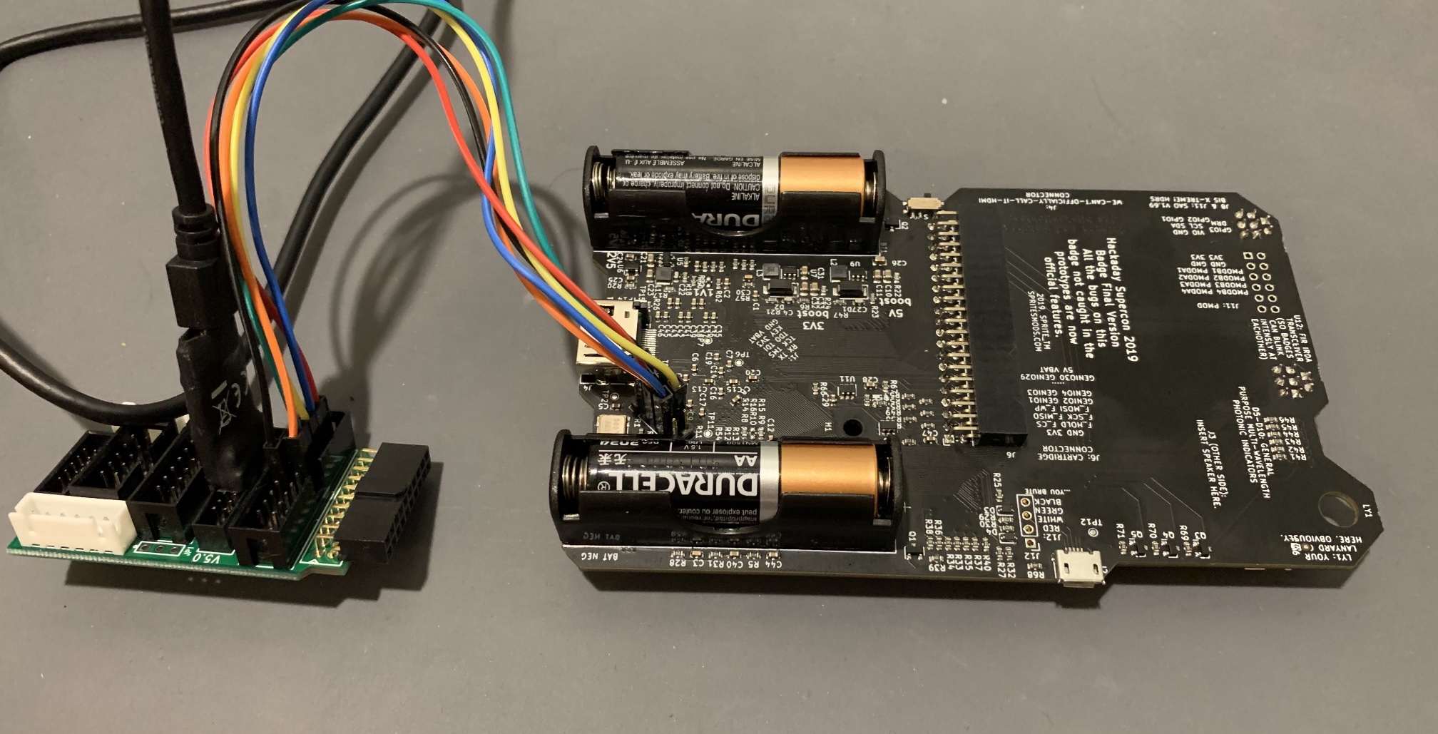 The extra board is an adapter from the HS3 2mm pitch connector to a more common 0.1" pitch connector that is compatible with these hookup wires
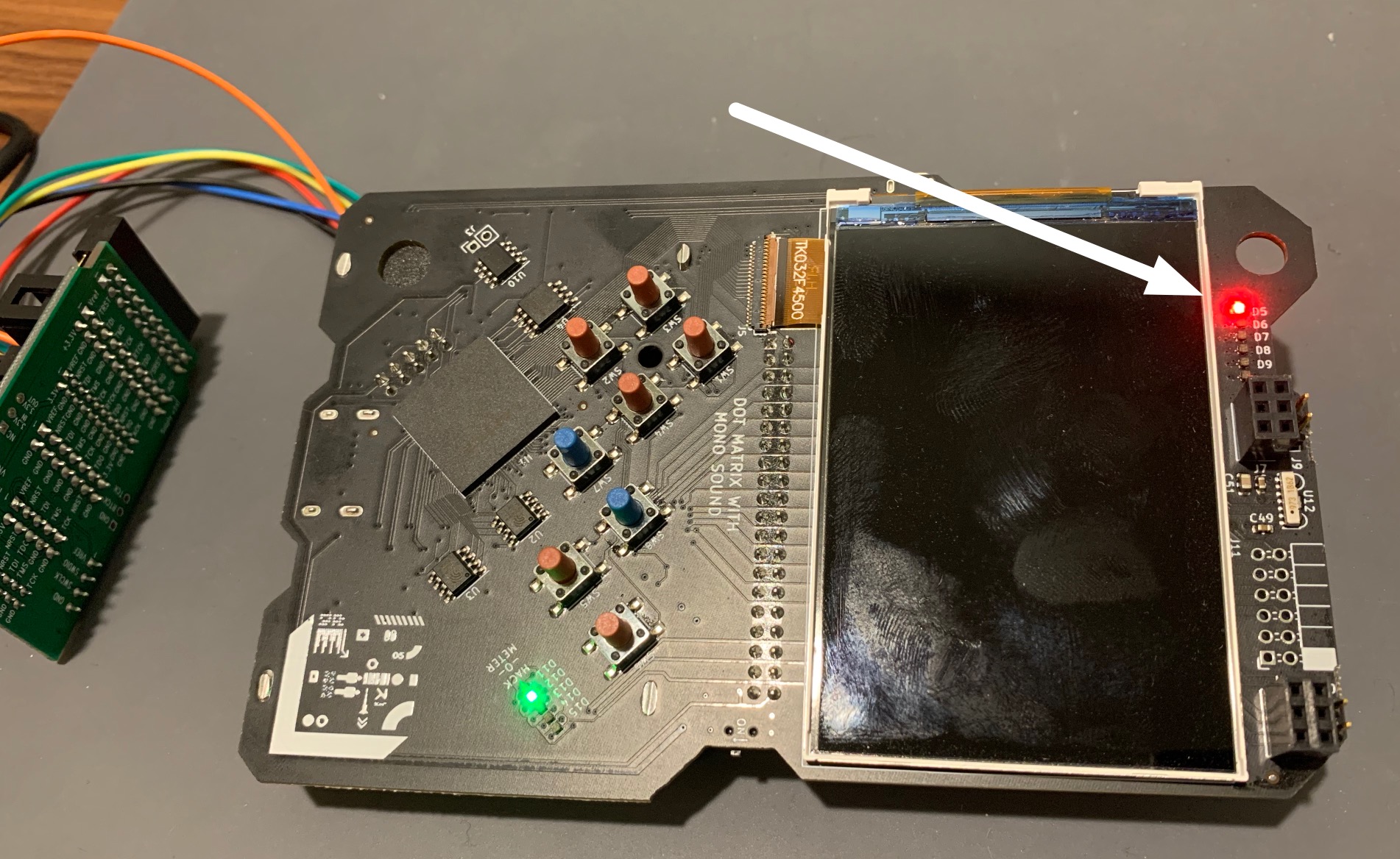
If you also have a Supercon badge, here’s a picture of the pinout for reference:
Now finally, we can run the OpenOCD command to actually program the device:
openocd -f openocd.cfg -c "init; svf $<; exit"
This passes in our OpenOCD config to setup the adapter, then uses the generated SVF file from ecppack to actually send the configuration over JTAG. After loading the configuration, the first LED on the top of the badge should be solidly lit up.
It’s actually a bit simpler to use a Makefile to automate all of these steps. Instead of running all the commands separately, we can just run make or make prog to load onto the FPGA. Check out the Makefile here.
The code so far for the solidly lit LED is available on this branch on Github.
Blinky using a counter
Now that we’ve tested out the full toolchain all the way to the FPGA, let’s make the bitstream a little bit more interesting. To make a blinky LED we need to set up a counter, feed it with a clock, and toggle the LED when the counter hits some value. The SpinalHDL standard library actually provides a counter component that we can just use. The only slightly involved part is setting up a clock domain driven by the external clock onboard the Supercon badge, and configuring that domain to reset on boot without an externally driven reset line. By default, SpinalHDL components that have sequential logic include a clock and reset IO (doesn’t have to be explicitly defined in the IO bundle). Here, for our top-level component, we don’t want a reset line though, just a clock.
class Blinky extends Component {
    val io = new Bundle {
        val led = out Bool
    }

    val externalClockDomain = ClockDomain.external(
        "", // resulsts in a clk IO named "clk"
        ClockDomainConfig(resetKind=BOOT) // does not generate a reset IO
    )

    new ClockingArea(externalClockDomain) {
        // register for current state of the LED
        val toggle = RegInit(False)
        // counter with 8 million states set to auto-increment
        when (Counter(8 * 1000 * 1000, inc=True).willOverflow) {
            toggle := !toggle
        }

        io.led := toggle
    }

    noIoPrefix()
}
We also need to add another I/O to the .lpf file, since now the design needs an external clock input.
#8MHz clock
LOCATE COMP "clk" SITE "U18";
IOBUF PORT "clk" IO_TYPE=LVCMOS33;

#LEDs
LOCATE COMP "led" SITE "E3";
IOBUF PORT "led" IO_TYPE=LVCMOS33;
With sbt and the Makefile automation, elaborating, synthesizing, placing, routing, and loading the new FPGA bitstream is easy:
make prog
I actually added an additional dependency in the Makefile to automatically run sbt as well. The code for the counter blinky is available in this branch on Github.
Blinky with RiscV
RiscV has been quickly gaining popularity lately. In fact, the Hackaday Supercon badge default bitstream runs an FPGA SoC based on dual RiscV CPUs (PicoRV32). PicoRV32 is written in Verilog, and while it is easy to use Verilog modules from SpinalHDL, I want to use the VexRiscv soft core, written in SpinalHDL itself. By leveraging the expressiveness of SpinalHDL, the VexRiscv project can generate RiscV cores ranging from the smallest microcontroller to a full Linux capable CPU with an MMU. The project does this using a plugin system, where even new instructions can be added with plugins. VexRiscv is also gaining popularity, and is used in the LiteX RiscV Linux project.
Adding VexRiscv as a dependency to the blinky project is pretty simple–just a few lines at the end of the build.sbt file. Here I’m adding the project as a git dependency, so I get the latest and greatest from the master branch.
Note: Scala’s built.sbt no longer requires you to make a separate Scala build script file to include dependencies like this. The code below can go right at the end of build.sbt. Sweet.
lazy val root = Project("root", file("."))
    .dependsOn(vexRiscV)
lazy val vexRiscV = RootProject(uri("https://github.com/SpinalHDL/VexRiscv.git"))
Instantiating the VexRiscv core takes two steps: first we configure the plugins we want to use, and then we instantiate the component using the plugin config. I won’t paste all the code here (check out this branch on the repo), but we’ll go through the important bits.
First, the plugin configuration:
val vexRiscVPlugins = ArrayBuffer(
    new PcManagerSimplePlugin(0x00000000l, false),
    new IBusSimplePlugin(
        resetVector = 0x00000000l,
        cmdForkOnSecondStage = true,
        cmdForkPersistence  = true
    ),
    new DBusSimplePlugin(
        catchAddressMisaligned = false,
        catchAccessFault = false
    ),
    new DecoderSimplePlugin(
        catchIllegalInstruction = false
    ),
    new RegFilePlugin(
        regFileReadyKind = plugin.SYNC,
        zeroBoot = true
    ),
    new IntAluPlugin,
    new SrcPlugin(
        separatedAddSub = false,
        executeInsertion = false
    ),
    new LightShifterPlugin,
    new HazardSimplePlugin(
        bypassExecute           = false,
        bypassMemory            = false,
        bypassWriteBack         = false,
        bypassWriteBackBuffer   = false
    ),
    new BranchPlugin(
        earlyBranch = false,
        catchAddressMisaligned = false
    ),
    new CsrPlugin(
        config = CsrPluginConfig(
        catchIllegalAccess = false,
        mvendorid      = null,
        marchid        = null,
        mimpid         = null,
        mhartid        = null,
        misaExtensionsInit = 66,
        misaAccess     = CsrAccess.NONE,
        mtvecAccess    = CsrAccess.NONE,
        mtvecInit      = 0x80000020l,
        mepcAccess     = CsrAccess.READ_WRITE,
        mscratchGen    = false,
        mcauseAccess   = CsrAccess.READ_ONLY,
        mbadaddrAccess = CsrAccess.READ_WRITE,
        mcycleAccess   = CsrAccess.NONE,
        minstretAccess = CsrAccess.NONE,
        ecallGen       = false,
        wfiGenAsWait         = false,
        ucycleAccess   = CsrAccess.NONE
        )
    )
)
I based my configuration on the Briey demo in the VexRiscv repository. This demo configures a minimal core that will run embedded C or Rust. Check out the plugin docs for more information about each.
Next, the CPU instantiation:
val vexRiscVConfig = VexRiscvConfig(plugins = vexRiscVPlugins)
val cpu = new VexRiscv(vexRiscVConfig)
var iBus : Axi4ReadOnly = null
var dBus : Axi4Shared = null
for (plugin <- vexRiscVConfig.plugins) plugin match {
    case plugin : IBusSimplePlugin => iBus = plugin.iBus.toAxi4ReadOnly()
    case plugin : DBusSimplePlugin => dBus = plugin.dBus.toAxi4Shared()
    case plugin : CsrPlugin => {
        plugin.externalInterrupt := False
        plugin.timerInterrupt := False
    }
    case _ =>
}
For now, I’ve just tied off both interrupts to False. The IBusSimplePlugin and DBusSimplePlugin provide uncached memory access over the Axi4 buses configured above–perfect for fast memories in the FPGA fabric. For off-chip memories, you’d definitely want to use the cached plugin variants.
We’re also going to need some memory to store the program and stack and, and we’re also going to need a register to drive the LED outputs (I decided to drive all of the LEDs at the top of the badge this time).
// Who ever needed more than 4kB of RAM?
val ram = Axi4SharedOnChipRam(
    dataWidth = 32,
    byteCount = 4 kB,
    idWidth = 4
)

// APB is a much simpler bus for peripherals like an LED register
val apbBridge = Axi4SharedToApb3Bridge(
    addressWidth = 32,
    dataWidth = 32,
    idWidth = 0
)

// Map the APB peripheral bus onto the AXI4 address space using a crossboar
val axiCrossbar = Axi4CrossbarFactory()
axiCrossbar.addSlaves(
    ram.io.axi       -> (0x00000000L, 4 kB),
    apbBridge.io.axi -> (0x10000000L,   1 MB)
)

// The SpinalHDL AXI crossbar is super flexible and let's you define the
// cross-connections that are possible.
axiCrossbar.addConnections(
    iBus -> List(ram.io.axi),
    dBus -> List(ram.io.axi, apbBridge.io.axi)
)

axiCrossbar.build()

// Adding a register on the APB bus is super simple using the slave factory interface
// Normally, you would put this in a peripheral component, but for now we'll just
// leave this all in one
val ledReg = Apb3SlaveFactory(apbBridge.io.apb)
    .createReadWrite(Bits(6 bits), 0x10000000L, 0)
io.leds := ledReg
The last bit of SpinalHDL, to generate the LED output register makes use of the standard library’s Bus Slave Factory. Each bus in the standard library implements the slave factory to simplify adding registers at address offsets with different read/write characterics
The only other complicated part is properly resetting an AXI4 bus. the AXI spec says that the reset must last at least 64 clock cycles. So, on boot, the Blinky component needs to hold the CPU and AXI bus in reset for a bit.
val resetCtrlDomain = ClockDomain.external(
    "",
    ClockDomainConfig(resetKind=BOOT)
)

// AXI spec requires a long reset
val resetCtrl = new ClockingArea(resetCtrlDomain) {
    val systemReset = RegInit(True)
    val resetCounter = RegInit(U"6'h0")
    when (resetCounter =/= 63) {
        resetCounter := resetCounter + 1
    } otherwise {
        systemReset := False
    }
}

val coreDomain = ClockDomain(
    clock = resetCtrlDomain.readClockWire,
    reset = resetCtrl.systemReset
)
First we create a reset domain that resets on BOOT (on FPGA configuration). In that domain we create a counter up to the 64 cycles required, and then that counter drives the reset for the clock domain used by the CPU and AXI bus (the full code is on this branch).
Now we need a bit of firmware to run on the CPU!
Just to test and make sure that VexRiscv configuration works and that the buses are hooked up correctly, I’m going quickly write a program in RiscV assembly. I found a decent RiscV assembly instruction reference, and I learned the most important part (to me) was the pseudo-instruction table. There a bunch of jumps and branches possible, so letting the assembler pick the right ones based on my pseudo-instruction is convenient.
.section .text
.globl _start
_start:
    li x5, 0x1
    li x28, 0x20
    li x6, 0x10000000

outer:
    li x7, 0x40000
loop0:
    sub x7, x7, x5
    bne x7, x0, loop0
    sw x28, 0(x6)
    srli x28, x28, 1
    beq x28, x0, reset
    j outer
reset:
    li x28, 0x20
    j outer
You may have noticed that I didn’t include a vector table at all. For this simple test, we don’t have any interrupt sources, and shouldn’t have any exceptions triggered. So, the CPU will boot to address 0x00000000 and start executing code from _start:. The program itself consists of a delay loop that cycles which LED is turned on using a shift instruction.
To assemble the code we use GNU as:
riscv64-unknown-linux-gnu-as -o blink.out blink.s
You can actually take a peek at the final generated assembly pretty easily with GNU objdump:
riscv64-unknown-linux-gnu-objdump -d blink.out
This will dump the disassembly with the final concrete instructions and addresses.
blink.out:     file format elf64-littleriscv


Disassembly of section .text:

0000000000000000 <_start>:
   0:   00100293                li      t0,1
   4:   02000e13                li      t3,32
   8:   10000337                lui     t1,0x10000

000000000000000c <outer>:
   c:   000403b7                lui     t2,0x40

0000000000000010 <loop0>:
  10:   405383b3                sub     t2,t2,t0
  14:   fe039ee3                bnez    t2,10 <loop0>
  18:   01c32023                sw      t3,0(t1) # 10000000 <reset+0xfffffd8>
  1c:   001e5e13                srli    t3,t3,0x1
  20:   000e0463                beqz    t3,28 <reset>
  24:   fe9ff06f                j       c <outer>

0000000000000028 <reset>:
  28:   02000e13                li      t3,32
  2c:   fe1ff06f                j       c <outer>
To output the assembled code as binary that we can load into the FPGA memory, we use GNU objcopy:
riscv64-unknown-linux-gnu-objcopy -O binary blink.out blink.bin
This is all automated with a simple makefile in the firmware directory.
And, now that we have a binary to load into the memory, we need to initialize the RAM with it during elaboration. I created a helper function, loadProgram that loads the program bytes with the correct endianness, and then pads out the loaded program with zeroes to the size of the AXI RAM we defined above.
object BlinkySpinalConfig extends SpinalConfig(mode = Verilog)

object BlinkyVerilog {
    def loadProgram(path: String, padToWordCount: Int): Array[BigInt] = {
        Files.readAllBytes(Paths.get(path))
            .grouped(4)
            .map(wordBytes => {
                BigInt(new BigInteger(
                    wordBytes.padTo(8, 0.toByte).reverse.toArray))
            })
            .padTo(padToWordCount, BigInt(0))
            .toArray
    }

    def main(args: Array[String]) {
        val program = loadProgram("firmware/blink.bin", 1024)

        BlinkySpinalConfig.generateVerilog({
            val top = new Blinky
            top.core.ram.ram.initBigInt(program)
            top
        })
    }
}
Finally, we can run make prog in the top-level directory to kick off elaboration all the way to bitstream generation and programming. The Supercon badge should show a bit more interesting behavior after this bitstream is loaded!
Blinky with Rust on RiscV
Now that VexRiscv runs and we have a way to load a program, I want to run embedded Rust on this thing! It turns out that setting up Rust for embedded Risc-V development is similar to embedded ARM development. If you haven’t done any embedded Rust, check out my getting started guide for Rust on STM32. There are two main crates in the embedded Rust RiscV ecosystem right now:
riscv: this crate provides minimal low-level RiscV assembly functions, access to CSRs, and interrupt control. This crate is analoguous to cortex-m for STM32.
riscv-rt: this crate provides the minimal startup code to execute Rust on embedded Risc-V and link a binary. The docs for this crate also give a very nice (but not explained well) guide to starting an embedded Risc-V project.
To get started, we’re going to blow away the current contents of the firmware directory and start a rust project:
rm -r firmware/*
cd firmware
cargo init .
cargo init is similar to the cargo new you are probably familiar with, but it just creates a project in the existing directory instead of creating a new one.
Next we need to add riscv-rt to our Cargo dependencies (it will include the riscv crate for us).
[package]
name = "blinky"
version = "0.1.0"
authors = ["Craig Bishop <craig@craigjb.com>"]
edition = "2018"

[dependencies]
riscv-rt = "0.6.1"
panic-halt = "0.2.0"

[profile.release]
codegen-units = 1 # better optimizations
debug = true # symbols are nice and they don't increase the size on Flash
lto = true # better optimizations
Those release profile flags are pretty typical for embedded Rust projects. For embedded, we want the smallest binary size we can get!
Note: debug symbols do not take up flash memory on your microcontroller (or RAM in this case). They are only used host side to map addresses to symbol names.
Next, we need to setup the linker memory map for our Risc-V FPGA system. Just like with a STM32 project, this is done using a file called memory.x:
MEMORY
{
  RAM : ORIGIN = 0x00000000, LENGTH = 4K
}

REGION_ALIAS("REGION_TEXT", RAM);
REGION_ALIAS("REGION_RODATA", RAM);
REGION_ALIAS("REGION_DATA", RAM);
REGION_ALIAS("REGION_BSS", RAM);
REGION_ALIAS("REGION_HEAP", RAM);
REGION_ALIAS("REGION_STACK", RAM);
Unlike the examples in the riscv-rt docs, our FPGA Risc-V system only has RAM, and the program is already in the RAM on boot. So I modified memory.x to put everything into RAM, code, stack, static data, etc.
Now, we’ll create our application code in src/main.rs:
// inline asm is still a nightly feature
#![feature(asm)]

// embedded projects don't use std because it relies on dynamic memory allocation
#![no_std]
// embedded projects have specialized startup code (in the riscv crate)
// so, we don't have a "predefined" main function
#![no_main]

extern crate panic_halt;

use riscv_rt::entry;

// simple delay look using inline asm so it doesn't get optimized away
fn delay(cycles: u32) {
    for _ in 0..cycles {
        unsafe {
            asm!("nop");
        }
    }
}

// here, I wrap unsafe register access to make it safe
// in a bigger project, you'd probably create a hierarchy of structs
// to represent the peripherals
fn set_leds(mask: u32) {
    unsafe {
        *(0x10000000 as *mut u32) = mask;
    }
}

// the #[entry] macro tells riscv-rt what function to run on startup
#[entry]
fn main() -> ! {
    let mut mask = 0x40;
    loop {
        set_leds(mask);
        mask >>= 1;
        if mask == 0 {
            mask = 0x40;
        }
        delay(300000);
    }
}
To actually compile this project, we’re going to need to install the Rust Risc-V target, and setup our project to use it.
If you aren’t already using it, rustup is best way to install and update Rust. It also lets us easily install new targets like Risc-V. I’m using nightly here because the inline assembly for nop still requires nightly to work.
rustup target add --toolchain nightly riscv32imac-unknown-none-elf
And, now we need to configure Cargo to use nightly and this target for our project.
echo "nightly" > rust-toolchain
A rust-toolchain file in your project directory can control whether rustup uses stable or nightly for your build.
We can crate a directory and file at .cargo/config to control what target Cargo builds our project for:
[target.riscv32imac-unknown-none-elf]
rustflags = [
  "-C", "link-arg=-Tmemory.x",
  "-C", "link-arg=-Tlink.x",
]

[build]
target = "riscv32imac-unknown-none-elf"
We also have to create a build script, build.rs, to include the memory map we created earlier. Check it out on this branch in the repository.
Finally, we can run cargo build --release, and generate a binary we can load onto the FPGA.
You can take a peek at the disassembly to see what the Rust startup looks like:
riscv64-unknown-linux-gnu-objdump -d target/riscv32imac-unknown-none-elf/release/blinky
Also, just like in my STM32 guide, I use the cargo make plugin to automate stripping unnecessary data from the executable and converting it to a binary form for loading into the FPGA memory.
Here’s the Makefile.toml:
[tasks.strip]
command = "riscv64-unknown-linux-gnu-strip"
args= [
    "target/riscv32imac-unknown-none-elf/release/blinky",
]

[tasks.objcopy]
command = "riscv64-unknown-linux-gnu-objcopy"
args= [
    "-O", "binary",
    "target/riscv32imac-unknown-none-elf/release/blinky",
    "target/riscv32imac-unknown-none-elf/release/blinky.bin"
]
dependencies = ["strip"]
With these directives, we can run cargo make objcopy to create a binary file that can be loaded into the FPGA memory.
And then, we just have to point the memory initialization to the new binary:
def main(args: Array[String]) {
    val program = loadProgram("firmware/target/riscv32imac-unknown-none-elf/release/blinky.bin", 1024)

    BlinkySpinalConfig.generateVerilog({
        val top = new Blinky
        top.core.ram.ram.initBigInt(program)
        top
    })
}
Now, if we run make prog, we should see Rust code running on Risc-V on the FPGA! It looks… the same. But, that was expected :)
All of the code for Rust on RiscV on Symbiflow on the Supercon badge is available on this branch on the repository.
Appendix - Installing the SymbiFlow tools
If you are on macOS or Windows, or don’t mind not having the absolutely latest, then download this prebuilt toolchain from xobs. It even includes Risc-V gcc.
If you want to build from source, here’s how on Ubuntu (everything except dependency installation should work on other Linux variants).
Warning: Installing from source can temporarily take up quite a bit of disk. For example, the Risc-V toolchain repository checks out so many sub-modules it can balloon to over 10 GB. You can delete this bloat after you’re done building though.
Building and installing trellis
I followed the build instructions on the Github readme.
-
Install build dependencies (only tested on Ubuntu)
sudo apt-get install libboost-all-dev python3 python3-pip build-essential cmake git openocd -
Clone into trellis
git clone --recursive https://github.com/SymbiFlow/prjtrellis -
Build and install trellis (prefix is up to you, some people like
/optor/tools)cd libtrellis cmake -DCMAKE_INSTALL_PREFIX=/usr/local . make -j$(nproc) sudo make install
Build and install Yosys
I followed the build instructions on the Github readme.
-
Install build dependencies
sudo apt-get install build-essential clang bison flex libreadline-dev gawk tcl-dev libffi-dev git graphviz xdot pkg-config python3 libboost-system-dev libboost-python-dev libboost-filesystem-dev zlib1g-dev -
Clone into yosys
git clone https://github.com/YosysHQ/yosys.git -
Build and install yosys
 cd yosys
 make -j$(nproc)
 sudo make install PREFIX=/usr/local
Build and install nextpnr
I followed the build instructions on the Github readme.
-
Install build dependencies (assumes previous dependencies are also installed)
sudo apt-get install qt5-default python3-dev libboost-all-dev libeigen3-dev -
Clone into nextpnr
git clone https://github.com/YosysHQ/nextpnr.git -
Configure for ECP5
cd nextpnr cmake -DARCH=ecp5 -DTRELLIS_ROOT=/usr/local/share/trellis . -
Build and install
 make -j$(nproc) TRELLIS=
 sudo make install PREFIX=/usr/local
Build and install Risc-V toolchain (GCC and friends)
I followed the build instructions on the Github readme.
-
Install the build dependencies
sudo apt-get install autoconf automake autotools-dev curl libmpc-dev libmpfr-dev libgmp-dev gawk build-essential bison flex texinfo gperf libtool patchutils bc zlib1g-dev libexpat-dev -
Clone into the repository with sub-modules
git clone --recursive https://github.com/riscv/riscv-gnu-toolchain -
Build a Linux multilib toolchain (support for 32-bit and 64-bit Risc-V)
 ./configure --prefix=/opt/riscv --enable-multilib
 export MAKEFLAGS="-j$(nproc)"
 make linux
The
MAKEFLAGSvar helps the sub-module builds go faster when you have multi-core oomph. -
Add the toolchain to your PATH environment variable
This should go in your shell profile (.bash_profile, .zshrc, etc)
export PATH="$PATH:/opt/riscv/bin"