
STM32L0 Rust Part 1 - Getting Started
The embedded Rust development ecosystem is changing fast. A bunch has changed even since early 2019 when I started prototyping firmware for the Gameslab’s system controller (STM32L0). Most of the changes are incredible! Device support crates, hardware abstraction layers (HALs), and even USB support are all very usable now for Cortex-M devices. In this post, I’ll summarize the ecosystem and show how to get started with embedded Rust on a STM32L0 part.
Embedded Rust ecosystem (for STM32 at least)
Cortex-M based parts are pretty well supported now in the Rust ecosystem. There’s a hierarchy of crates to add support for various things below your application or firmware code.
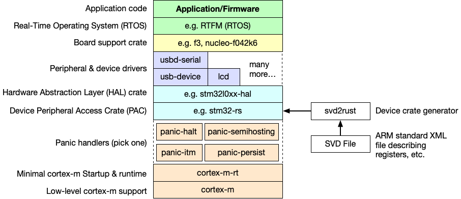
cortex-m: This crate provides low-level helpers specific to Cortex-M parts, such as toggling interrupts or assembly delay loops.
cortex-m-rt: This crate provides the startup code for Rust on Cortex-M parts. This is similar to crt.s for embedded C. This crate provides a vector table, exceptions, and the interrupt table.
Panic handlers: These provide different options for what to do upon a Rust panic. In an embedded system, you usually don’t have a terminal to dump a panic to. So, you can halt the processor, reset, dump to a debug port, keep the panic details in memory for next boot, etc. You pick one crate to use in your application.
Peripheral Access Crate (PAC): These crates provide helpers for accessing the registers on parts using a more type-safe Rust API. They are generated using a tool called svd2rust, which takes in a System View Description (SVD) xml file that describes all the registers and their bit-fields. This file is actually required by ARM from licensees. The vendor SVD files are not always great, so several projects have patched them to clean-up the peripheral access APIs. For example, the stm32-rs project has PACs for a bunch of STM32 parts.
<register>
    <name>OTYPER</name>
    <displayName>OTYPER</displayName>
    <description>GPIO port output type register</description>
    <addressOffset>0x4</addressOffset>
    <size>0x20</size>
    <access>read-write</access>
    <resetValue>0x00000000</resetValue>
    <fields>
    <field>
        <name>OT15</name>
        <description>Port x configuration bits (y =
        0..15)</description>
        <bitOffset>15</bitOffset>
        <bitWidth>1</bitWidth>
    </field>
    ...
    </fields>
</register>
Example snippet from an SVD file describing a GPIO port register. Remember XML, it’s fun isn’t it.
Hardware Abstraction Layer (HAL): HAL crates provide types and helpers for setting up clocks, driving peripherals, setting up interrupts, etc. There are HAL crates available for a variety of devices, of which STM32 parts are pretty decently supported (I’m using stm32l0xx-hal for my STM32L073 part). Some of them even implement traits from embedded-hal, a project trying to standardize some traits for accessing peripherals like I2C, SPI, etc. The dream is that we can write Rust crates for interacting with an I2C slave using the embedded-hal API, and then re-use that crate across different HALs on different devices.
Peripheral and device drivers: These crates provide drivers for some peripherals (like USB) and for other devices over I2C, SPI, or other buses. The idea is that using embedded-hal, we can create drivers for chips that are agnostic of what microcontroller you are using. If it implements the embedded-hal traits for the communication interface (e.g. SPI, I2C), then the driver crate can talk to it. The dream is slowly coming about, and there is a partial list of driver crates built on top of embedded-hal here.
Board Support Crate (BSC): These crates put together the lower-level crates (drivers, HAL, and PAC) to form a crate supporting a microcontroller plus the peripherals on the circuit board around it. In these crates, the API is in terms of the parts on the board, for example status_led.on(), instead of gpioa.pb10.set_high(). If you created a board that others are going to use, it’s a good idea to create a BSC. If others are not likely to use your board (like the Gameslab system management controller), the board-support code might be included in the application crate.
Real-Time Operating System (RTOS): Real-time operating systems provide a layer on top of the bare-metal hardware for managing the execution of concurrent tasks and interrupts. Unlike a full OS, these typically do not provide IO, file systems, security, or things like that. Typically a RTOS provides an API for defining tasks and their relative priorities. High-priority tasks can then preempt lower priority tasks to ensure real-time constraints. The canonical example of an RTOS is FreeRTOS written in C, which is very widely used. In Rust-land, we have a project called Real Time For the Masses (RTFM) which provides many RTOS features, with compile-time checking of concurrent access to peripherals. For example, you will get compiler warnings if you try to use the same peripheral in two interrupts (same priority) without locking. RTFM is simple enough and has low overhead, so I find myself using it on most of my projects, even just to organize handlers for interrupts.
Application/Firmware: This is your code! In my case, this is the system management firmware for the Gameslab that manages the battery, voltage and current monitoring, the real-time clock, a couple LEDs, and boots the main Zynq part.
If you like a different style, this great tweet from James Munns (@bitshiftmask) also maps out the embedded Rust crates. If you click through to his Twitter, he’s posted more pages too.
Trying out a new medium for blog posts: a sketch-notes style one pager of technical ideas in my head (usually @rustlang /@rustembedded). Let me know what you think of the format :) pic.twitter.com/un2sl3MhxI
— James Munns (@bitshiftmask) December 28, 2019
Grabbing the tools
- Make sure you have Rust and Cargo installed with rustup
-
Add the appropriate ARM target for your device:
rustup target add thumbv6m-none-eabiIf you have something other than a Cortex-M0+ (STM32L0), check this page for what target you should add.
- Install an ARM GCC toolchain. Rust will need it for linking the final binary.
- On Ubuntu or Debian:
apt-get install gcc-arm-none-eabi binutils-arm-none-eabi - On MacOS, grab a pre-built toolchain from the homebrew-arm repo
- I don’t do Windows…
- On Ubuntu or Debian:
Over the last year, I’ve begrudgingly converted from terminal VIM to VSCode with VIM mode as my editor of choice, and it has pretty good Rust support through the Rust Language Server (RLS). I never thought I’d want to run an Electron app as my main editor, but the extensions, remote editing, and auto-complete work really well out-of-the-box.
Starting the project
The embedded Rust community has created a template Github repository that makes getting started on Cortex-M microcontrollers super easy. You will need to install the cargo-generate utility, and then run a generate command.
cargo install cargo-generatecargo generate --git https://github.com/rust-embedded/cortex-m-quickstart.- Enter your project name when prompted, cargo will create a folder for the project
Next we need to pick a target. The Gameslab SMC is a STM32L0 Cortex-M0, so it runs thumb6m code, but the Cortex-M3 and Cortex-M4 parts run thumb7 code and have an optional FPU. Make sure to pick the right target for your part.
In the .cargo/config build section, uncomment the target corresponding to your device. In my case, I un-commented the thumb6m target. We’ll come back to this file later to define the runner for loading the binary onto the device.
[build]
# Pick ONE of these compilation targets
target = "thumbv6m-none-eabi"    # Cortex-M0 and Cortex-M0+
# target = "thumbv7m-none-eabi"    # Cortex-M3
# target = "thumbv7em-none-eabi"   # Cortex-M4 and Cortex-M7 (no FPU)
# target = "thumbv7em-none-eabihf" # Cortex-M4F and Cortex-M7F (with FPU)
We also have to tell the linker about the flash and SRAM layout of the device. The quick-start template creates a memory.x file in the project folder for this. Edit the MEMORY section of this file with the memory offsets and sizes from your device. My STM32L0 part has 64k of flash and 20k of SRAM.
MEMORY
{
  /* NOTE 1 K = 1 KiBi = 1024 bytes */
  /* TODO Adjust these memory regions to match your device memory layout */
  FLASH : ORIGIN = 0x08000000, LENGTH = 192K /* STM32L073RZ */
  RAM : ORIGIN = 0x20000000, LENGTH = 20K /* STM32L073RZ */
}
Finally, we can do a cargo build and get a binary that will run on our device. It will show up in the target/<target>/<debug|release> folder. For Gameslab, I have an ELF binary at target/thumbv6m-none-eabi/debug/gameslab-smc. This binary won’t do anything interesting though, since the entry function just contains a nop instruction for now.
Getting to blinky
This is where things start to diverge a bunch depending on your specific device (which HAL you use) and your board. For my board, I needed to pull in the device peripheral access crate (PAC) and HAL with a simple addition to Cargo.toml.
[dependencies.stm32l0]
version = "0.9.0"
features = ["stm32l0x3", "rt"]

[dependencies.stm32l0xx-hal]
git = "https://github.com/craigjb/stm32l0xx-hal.git"
features = ["stm32l0x3", "rt", "disable-linker-script"]
The features list specifies which device to use out of the crate, since these crates support many. Also, the disable-linker-script feature for the HAL disable its built-in memory.x file, since it doesn’t support my specific part (otherwise it can provide memory.x for you). I’m also using my personal fork of the HAL, since I have fixed a few things (I am issuing PRs as I go).
Now in main.rs we can get to business. The quick-start template generates these panic handler options for you, just make sure what you pick matches your cargo.toml too.
// pick a panicking behavior
extern crate panic_halt; // you can put a breakpoint on `rust_begin_unwind` to catch panics
// extern crate panic_abort; // requires nightly
// extern crate panic_itm; // logs messages over ITM; requires ITM support
// extern crate panic_semihosting; // logs messages to the host stderr; requires a debugger
Even though the extern crate syntax is deprecated in Rust 2018, it’s nicer in this case than use because we’re not actually using any function, just linking in the panic handler (otherwise you will see unused import warnings).
Now let’s put together a simple blinky program using a delay loop.
use cortex_m_rt::entry;

#[entry]
fn main() -> ! {
    loop { }
}
Here we import the entry attribute to mark the entry point for our application that will be called by the underlying cortex-m-rt after it sets up a stack for us. The main function signature has a return type of !, which tells the compiler to check that this function does not ever return. For embedded applications, returning from main isn’t meaningful–there’s no OS to return to.
use cortex_m_rt::entry;
use stm32l0::stm32l0x3;

#[entry]
fn main() -> ! {
    let peripherals = stm32l0x3::Peripherals::take().unwrap();
    loop { }
}
Next we take ownership of the top-level peripherals struct from the peripheral access crate (PAC). Peripherals::take() will only return Some(..) once so that the peripherals start with a single owner. HAL crates provide structs and functions to further split this top-level peripherals structure into sub-components that can be separately owned and mutated.
The embedded Rust ecosystem extensively uses Rust’s ownership model to prevent peripheral usage conflicts. At first, it seems kind of overbearing, but then the first time the compiler tells you that the I2C SDA pin you picked actually isn’t an IO MUX option for SDA, you will be happy.
Next we need to do a bit of clock configuration:
use cortex_m_rt::entry;
use stm32l0::stm32l0x3;
use stm32l0xx_hal::{prelude::*, rcc};

#[entry]
fn main() -> ! {
    let peripherals = stm32l0x3::Peripherals::take().unwrap();

    let clock_config = rcc::Config::pll(
        rcc::PLLSource::HSE(12.mhz()),
        rcc::PLLMul::Mul8,
        rcc::PLLDiv::Div4,
    );
    let mut rcc = peripherals.RCC.freeze(clock_config);

    loop { }
}
This sets up the Reset and Clock Control (RCC) peripheral using the frequency value of the crystal resonator on the Gameslab board (12 MHz) and dividers to give the PLL 96 MHz (needed for USB) and 24 MHz out to the system clock. Currently, the HAL crates out there provide a freeze method, which locks the clocks so that other peripherals can use the divided frequencies for calculating pre-scalers and other register values. There’s not really a good way yet to dynamically change clocks without de-initializing other peripherals first.
We need the mutable reference to the RCC returned by freeze for the next step:
use cortex_m_rt::entry;
use stm32l0::stm32l0x3;
use stm32l0xx_hal::{prelude::*, rcc};

#[entry]
fn main() -> ! {
    let peripherals = stm32l0x3::Peripherals::take().unwrap();

    let clock_config = rcc::Config::pll(
        rcc::PLLSource::HSE(12.mhz()),
        rcc::PLLMul::Mul8,
        rcc::PLLDiv::Div4,
    );
    let mut rcc = peripherals.RCC.freeze(clock_config);

    let gpiob = peripherals.GPIOB.split(&mut rcc);
    let mut status_led = gpiob.pb11.into_push_pull_output();

    loop { }
}
Here, the split method comes from the GpioExt trait imported with the HAL prelude. split takes the raw peripheral struct from the PAC and converts it into a struct that provides separate access and ownership for each GPIO pin, and also turns the GPIO clock on (this is why it needs to mutably borrow the RCC).
Note: the 12.mhz() is from an extension trait on the U32 type that adds the method mhz(), in addition to others.
Next, we configure GPIO PB11 into a push-pull output using into_push_pull_output(). If we take a look at the signature:
pub fn into_push_pull_output(self) -> PB11<Output<PushPull>>
Notice that the method consumes the original PB11 pin and returns a PB11<Output<PushPull>>. The Rust type of the pin is changed, and the original PB11<Input<Floating>> can’t be used. If you want to go back to a floating input, you’d have to release all ownership or borrows of the output pin and then call into_floating_input(). This makes sure that none of your code reconfigures pins that other code is relying on.
Note: cargo doc --open to load up local docs is incredibly useful here, since the embedded PAC and HAL crates make extensive use of macros to generate boilerplate. Looking at the code directly, it can be difficult to get a sense of what’s happening, but the generated docs aren’t bad (like the above signature). For example, the into_push_pull_output() signature looks like this in the source: pub fn into_push_pull_output(self) -> $PXi<Output<PushPull>>.
Now finally, we need to add some delays and toggle the LED in the loop. Here’s the full main.rs code:
#![no_std]
#![no_main]

extern crate panic_halt;

use cortex_m::asm::delay;
use cortex_m_rt::entry;
use stm32l0::stm32l0x3;
use stm32l0xx_hal::{prelude::*, rcc};

#[entry]
fn main() -> ! {
    let peripherals = stm32l0x3::Peripherals::take().unwrap();

    let clock_config = rcc::Config::pll(
        rcc::PLLSource::HSE(12.mhz()),
        rcc::PLLMul::Mul8,
        rcc::PLLDiv::Div4,
    );
    let mut rcc = peripherals.RCC.freeze(clock_config);
    let gpiob = peripherals.GPIOB.split(&mut rcc);
    let mut status_led = gpiob.pb11.into_push_pull_output();

    loop {
        status_led.set_high().unwrap();
        delay(12000000);
        status_led.set_low().unwrap();
        delay(12000000);
    }
}
Here I use a delay of 12,000,000 to toggle the LED roughly every second or two. Also, I haven’t mentioned the #![no_std] and #![no_main] at the top yet. These just instruct the Rust compiler not to include the standard library for us. On embedded targets, we don’t have a heap, which means no dynamic memory allocation, which means no standard library. We have to stick with what’s available in the Rust core crate. Also, since our embedded project uses it’s own startup code from cortex-m-rt, we don’t want Rust to assume a main function and generate startup code.
Since we setup the compile target in the cargo config file, we don’t have to do anything special now to build the project, just cargo build (or cargo build --release).
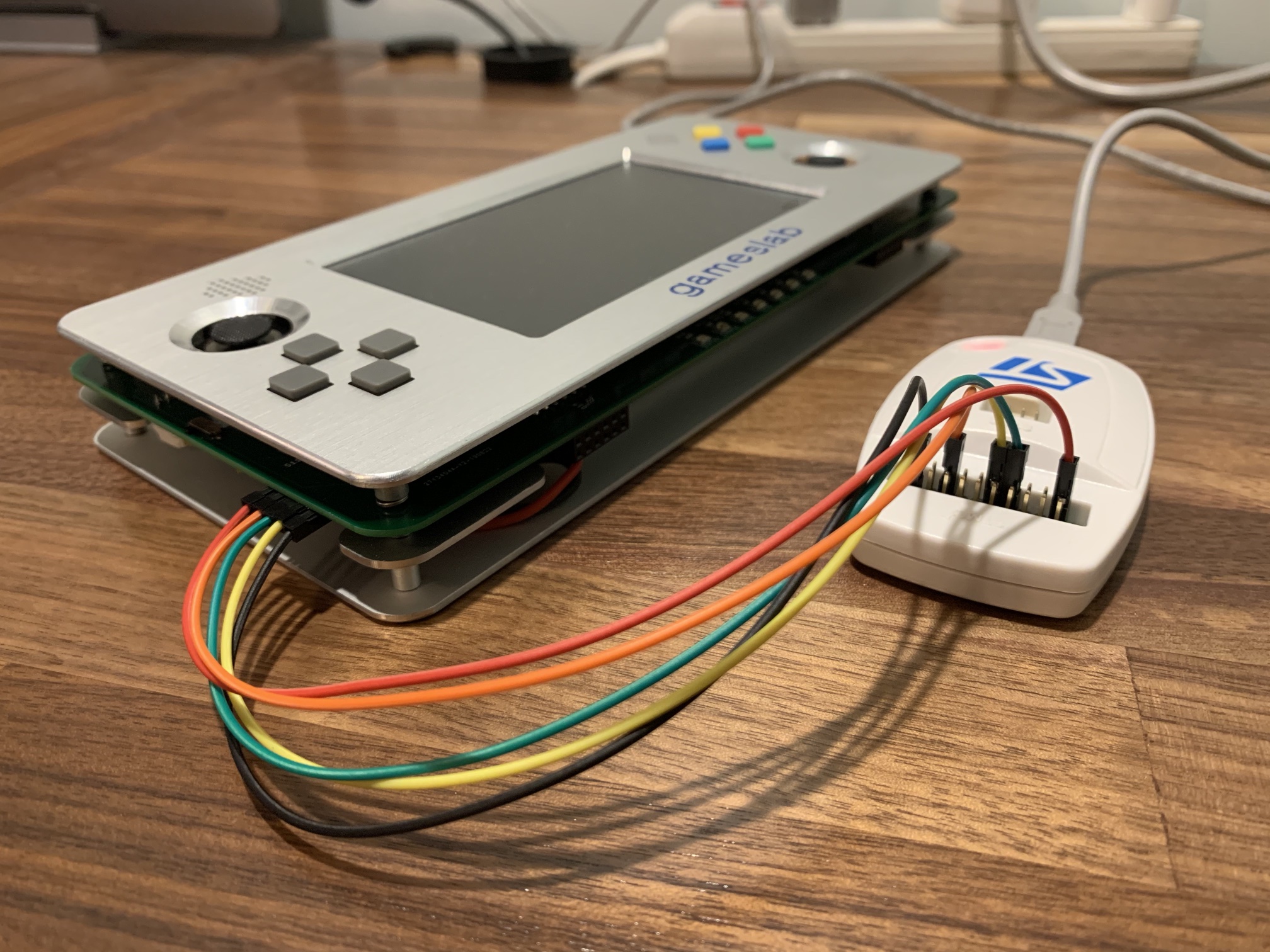
Programming the device
Getting our application onto the device involves using a USB JTAG or SWD (single-wire debug) adapter (such as a STLink) and OpenOCD. Wiring up the adapter to your board depends on your adapter’s pin-out and the pin-out of your board. For example, the Gameslab has this pin-out:
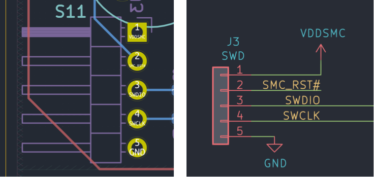
With the adapter connected, we just need an OpenOCD configuration file defining what adapter we’re using and what chip we’re trying to program or debug. The Cortex-M quick-start template comes with a openocd.cfg file, and I modified it to the below for my STLink-V2 and STM32L0 target (it’s pretty simple).
# OpenOCD configuration for the Gameslab
source [find interface/stlink-v2.cfg]
source [find target/stm32l0.cfg]
Now we can run OpenOCD, openocd -f openocd.cfg, and see the startup messages:
Open On-Chip Debugger 0.10.0
Licensed under GNU GPL v2
For bug reports, read
        http://openocd.org/doc/doxygen/bugs.html
Info : auto-selecting first available session transport "hla_swd". To override use 'transport select <transport>'.
adapter speed: 300 kHz
adapter_nsrst_delay: 100
Info : The selected transport took over low-level target control. The results might differ compared to plain JTAG/SWD
none separate
Info : Unable to match requested speed 300 kHz, using 240 kHz
Info : Unable to match requested speed 300 kHz, using 240 kHz
Info : clock speed 240 kHz
Info : STLINK v2 JTAG v29 API v2 SWIM v7 VID 0x0483 PID 0x3748
Info : using stlink api v2
Info : Target voltage: 3.266272
Info : stm32l0.cpu: hardware has 4 breakpoints, 2 watchpoints
Info : accepting 'telnet' connection on tcp/4444
The important part is that the adapter was detected and that OpenOCD started a telnet server on port 4444. We can now connect to that and issue OpenOCD commands. There is a plethora of commands available, but we’re only going to use the program command here.
>telnet localhost 4444

Trying 127.0.0.1...
Connected to localhost.
Escape character is '^]'.
Open On-Chip Debugger
>
After telnet connects to OpenOCD, we can issue the program command (with a reset afterward to start execution):
> program target/thumbv6m-none-eabi/debug/gameslab-smc reset

Unable to match requested speed 300 kHz, using 240 kHz
Unable to match requested speed 300 kHz, using 240 kHz
adapter speed: 240 kHz
target halted due to debug-request, current mode: Thread
xPSR: 0xf1000000 pc: 0x00003f4c msp: 0x20005000
STM32L0: Enabling HSI16
Unable to match requested speed 2500 kHz, using 1800 kHz
Unable to match requested speed 2500 kHz, using 1800 kHz
adapter speed: 1800 kHz
** Programming Started **
auto erase enabled
Device: STM32L0xx (Cat.5)
STM32L flash has dual banks. Bank (0) size is 128kb, base address is 0x8000000
couldn't use loader, falling back to page memory writes
wrote 12288 bytes from file target/thumbv6m-none-eabi/debug/gameslab-smc in 15.278187s (0.785 KiB/s)
** Programming Finished **
** Resetting Target **
Unable to match requested speed 300 kHz, using 240 kHz
Unable to match requested speed 300 kHz, using 240 kHz
adapter speed: 240 kHz
I don’t yet know what’s going on with the adapter speed messages, but it does program and reset successfully.
Blink has been achieved.
 Oh man! That blue really saturates the camera. I guess the current-limiting resistor on it is a bit low--it's really bright! That's what I get for guessing points on the LED current curves.
If you just want to program the device and exit OpenOCD, this one-liner avoids the need for telnet:
openocd -f openocd.cfg -c "program target/thumbv6m-none-eabi/debug/gameslab-smc reset"
Note: Here we are programming the binary from the debug configuration. Usually, you’ll want to use the release mode binary since it will be smaller and actually run at the speed you expect. The Rust optimization levels make a big difference!
Programming using the STM32L0 USB bootloader
A bunch of the STM32 devices come with a USB bootloader built-in that uses the Device Firmware Upgrade (DFU) protocol. With DFU, you can download new firmware to the device directly over its own USB device port. Activating the STM32 bootloader requires a button or jumper to pull the BOOT0 pin high. When BOOT0 is high and the device is reset, it will boot into a built-in ROM image containing the bootloader.

To flash the device using DFU, we’re going to need to convert our ELF binary into a raw binary file, without extra ELF headers or debug symbols. There’s a handy Cargo plugin called cargo-binutils. If you’ve done embedded development before, you may already be familiar with objcopy and other binutils friends. cargo-binutils adds a nice interface on top for using this tools in a Rust project. Install it with:
rustup component add llvm-tools-preview
cargo install cargo-binutils
You will need to install dfu-util:
- On Ubuntu or Debian:
apt-get install dfu-util - On MacOS:
brew install dfu-util
Now we can generate a binary file to upload with DFU:
cargo objcopy --bin gameslab-smc --release -- -O binary target/thumbv6m-none-eabi/release/gameslab-smc.bin
Once the board is in bootloader mode and connected to USB, we can check out the DFU interface:
>dfu-util -l
dfu-util 0.9

Copyright 2005-2009 Weston Schmidt, Harald Welte and OpenMoko Inc.
Copyright 2010-2016 Tormod Volden and Stefan Schmidt
This program is Free Software and has ABSOLUTELY NO WARRANTY
Please report bugs to http://sourceforge.net/p/dfu-util/tickets/

Found DFU: [0483:df11] ver=2200, devnum=11, cfg=1, intf=0, path="2-2.1", alt=2, name="@DATA Memory /0x08080000/2*3Ke", serial="154738430000"
Found DFU: [0483:df11] ver=2200, devnum=11, cfg=1, intf=0, path="2-2.1", alt=1, name="@Option Bytes  /0x1FF80000/01*032 e", serial="154738430000"
Found DFU: [0483:df11] ver=2200, devnum=11, cfg=1, intf=0, path="2-2.1", alt=0, name="@Internal Flash  /0x08000000/1536*128g", serial="154738430000"
The USB ID (0483:df11) is important for the -d argument in next step to actually program the device:
>dfu-util -d 0483:df11 -a 0 -s 0x08000000:leave -D target/thumbv6m-none-eabi/debug/gameslab-smc.bin
dfu-util 0.9

Copyright 2005-2009 Weston Schmidt, Harald Welte and OpenMoko Inc.
Copyright 2010-2016 Tormod Volden and Stefan Schmidt
This program is Free Software and has ABSOLUTELY NO WARRANTY
Please report bugs to http://sourceforge.net/p/dfu-util/tickets/

dfu-util: Invalid DFU suffix signature
dfu-util: A valid DFU suffix will be required in a future dfu-util release!!!
Opening DFU capable USB device...
ID 0483:df11
Run-time device DFU version 011a
Claiming USB DFU Interface...
Setting Alternate Setting #0 ...
Determining device status: state = dfuERROR, status = 10
dfuERROR, clearing status
Determining device status: state = dfuIDLE, status = 0
dfuIDLE, continuing
DFU mode device DFU version 011a
Device returned transfer size 2048
DfuSe interface name: "Internal Flash  "
dfu-util: Non-valid multiplier 'g', interpreted as type identifier instead
Downloading to address = 0x08000000, size = 572
Download        [=========================] 100%          572 bytes
Download done.
File downloaded successfully
Transitioning to dfuMANIFEST state
Question: I’m not quite sure what the -a 0 alt setting flag does. Can anyone explain if I’d ever want to use a non-zero value here?
A bit of automation
All of that is a bit wordy to type over and over in a workflow. So I use another Cargo plugin called cargo-make to run these tasks. It can be installed with cargo install cargo-make.
Then you can create a Makefile.toml file in your project folder and describe tasks to run and dependency relationships. I put these in:
[tasks.objcopy]
command = "cargo"
args= [
    "objcopy",
    "--bin", "gameslab-smc",
    "--release",
    "--",
    "-O", "binary",
    "target/thumbv6m-none-eabi/release/gameslab-smc.bin"
]

[tasks.dfu]
command = "dfu-util"
args = [
    "-d", "0483:df11",
    "-a", "0",
    "-s", "0x08000000:leave",
    "-D", "target/thumbv6m-none-eabi/release/gameslab-smc.bin"
]
dependencies = ["objcopy"]

[tasks.flash]
command = "openocd"
args = [
    "-f", "openocd.cfg",
    "-c", "program target/thumbv6m-none-eabi/release/gameslab-smc reset"
]
Now to download the program via OpenOCD, it’s as simple as cargo make flash. For DFU, cargo make dfu.
Code
The full code from this post on this tag in the Gameslab SMC firmware Github repo.