Fried by design and fried by accident
On the way to a working Gameslab, I had a few failures, some more “fun” than others. For example, it turns out that when your giant Zynq FPGA heats up to 70C while idling without any configuration, you might have a problem somewhere. Also, don’t solder while batteries are plugged in. Things die when you do. And, let’s not forget my newly found, strong distaste for QFP parts.
QFP aggravations
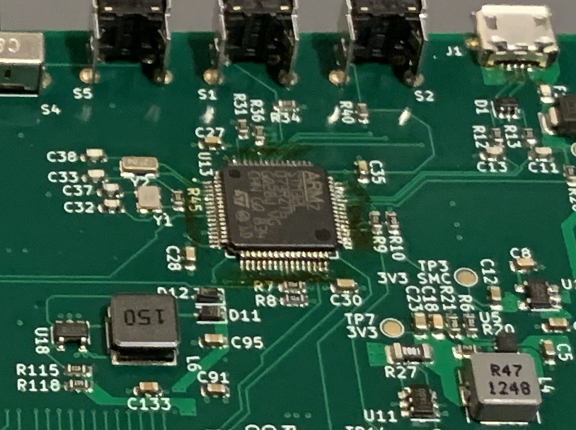
If you look closely in the picture below, you’ll see a bunch of ugly yellow flux residue around the STM32L073 LQFP-100 part. I had this problem after reflow on all three boards that I assembled. I double checked my stencil apertures, and they match the guidelines. Plus, I used the standard stencil thickness, so I don’t think I’m getting too much paste. Maybe my stencil alignment isn’t very good, but I’m not seeing any major problems on QFNs or the BGAs. Also, the only other part with 0.5 mm gull-wing leads like this, the 40-pin ZIF connector for the LCD also needed rework a couple times. Does anyone have experience with this? Or, are QFP parts always painful?
I’m probably going to switch to QFN for boards going forward. The QFN parts seem to tolerate more placement innaccuracy and the solder seems to flow better and not bridge. The BQ24250 battery charger, the USB PHY, the audio codec, and the class-D amp were all QFN.
Also, I should buy some no-clean flux. The flux-pen I have is just so convenient though!
Fried by design
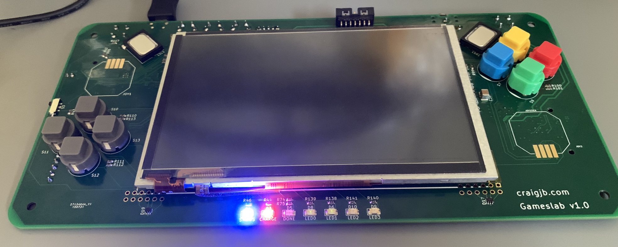
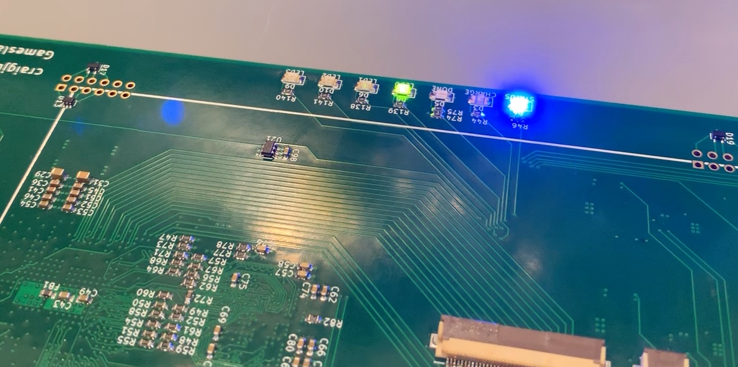
The first Gameslab board I assembled (assembly detailed here) mostly worked, which was pretty surprising to me! The bring-up process started with the STM32L0 supervisor MCU. Several of the LEDs are connected directly to it for debugging and displaying status. So, I wrote some barebones firmware (in embedded Rust of course!) to turn on the two LEDs and show that it lived at all. And, it worked, and showed how poorly I calculated the current-limiting resistors for the LEDs–they were bright!!
After verifying the STM32L073 lived, I fleshed out the firmware a bit further to enable the power rails to the Zynq, at first without releasing the Zynq from reset. This is when subtly weird things started to happen. When I measured the voltage rails with a multimeter, the 1.0 V, 1.5 V, and 1.8 V rails are looked just fine. However, when I measured the 3.3 V rail, I noticed more droop than I expected, down to 3.2-ish V and the current was really high, like 700 mA. That was way too high for a part that wasn’t doing anything! On top of that weird behavior, when I disabled the 3.3 V switching regulator, the output remained at ~0.7 V instead of falling to 0 V.
At this point, it looked like I had a short-circuit somewhere on the board. I crossed my fingers that it wasn’t under one of the BGAs and started probing around with a multimeter to see if I could track it down. After a bit, I really couldn’t find a short anywhere. The resistance measurements between each rail and ground looked fine. Odd.
Also, I was distracted from tracking down this problem because the system booted! I knew the Zynq was at least functional because it showed up via a JTAG dongle and I could peek and poke memory. So, I took the Zynq bare-metal blinky test and loaded it into RAM via JTAG. And, I sat in awe of the first blink! Awesome… for now.
The problem I had quietly ignored did not go away by itself. In fact, it came back to burn me, literally. While running the blinky test, I was holding the Gameslab with my fingers over the Zynq chip, and I noticed that the chip was getting uncomfortably hot very qickly.
The Zynq chip has a built-in temperature sensor connected to its XADC, and the Xilinx Vivado UI can show a live graph of the temperature it reads over JTAG. I plugged in the JTAG dongle, brought up the graph, and watched the temperature. Without anything running and with the processor halted via JTAG, the temperature climbed from room temperature up to 70 degrees C in minutes! Not good.
I thought for sure that my eBay source for these Zynq parts had gotten me. They must be faulty chips that heat up under no load for some reason.
Well, turns out that I was the problem. About a week later, I was trying to test out the buttons on the front of the board which are connected to one of the I/O banks on the FPGA fabric side of the Zynq. I couldn’t get the I/O to show any change at all on any of the buttons. I was getting desperate, so after double-checking my schematic, tracing the layout, and even probing the board for continuity, I got out the gigantic Zynq technical reference manual to fall asleep to. Somewhere in the manual, in a section about the I/O banks, it casually mentions that the HR I/Os tolerate up to 3.3 V and that the HP I/O tolerate up to 1.8 V standards. Oh… what’s a HR vs HP I/O?
Well, it turns out that these big Zynq parts with tons of I/O are split into “High-Range” and “High Performance” banks. The HR (high-range) banks are capable of 3.3 V I/O standards, like LVCMOS, but the HP (high-performance) banks are only capable up to 1.8 V with an absolute maximum rating of 2.5 V. Well, I had supplied all of the I/O banks from the 3.3 V rail, which would fry the internal ESD diodes and cause the Zynq to heat up. And, frying the internals explained the wonky readings on the 3.3 V rail.
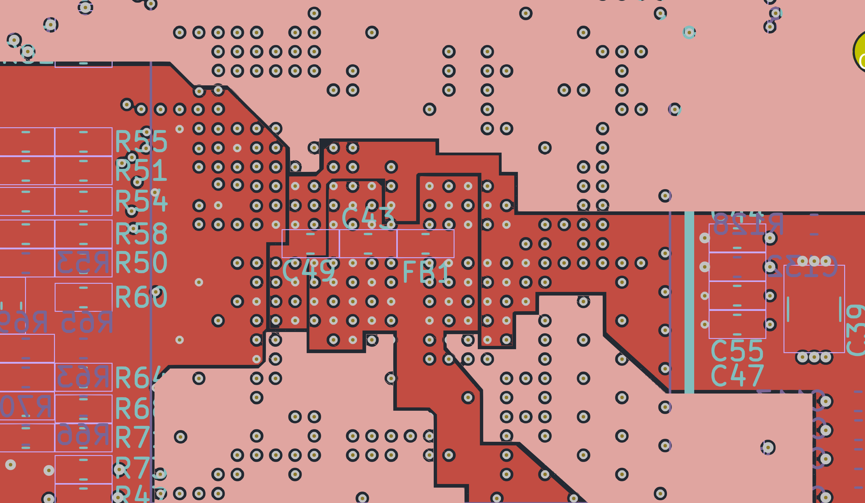 Painstakingly designed power islands supplying the Zynq HP I/O banks with deadly 3.3 V
As you can see in the above picture of the internal power islands, this wasn’t something I could fix with bodge wires. I needed a full re-spin of the board, and I had to re-route all the 3.3 V I/O to just the HR, 3.3 V capable, I/O banks. It ended up being quite the re-route too, since the HR banks are all in one corner.
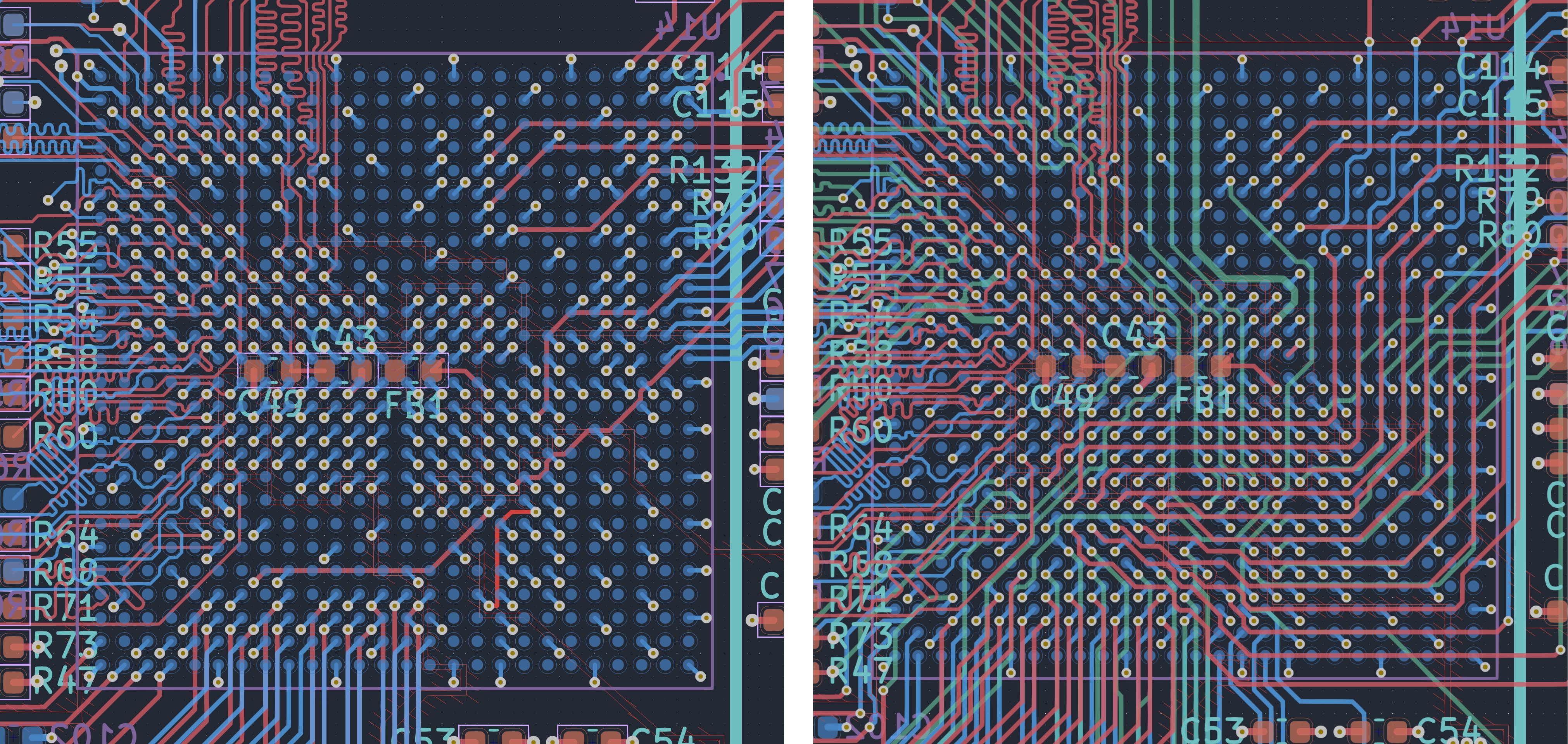 Left: before, I had all these open I/O and the routing was spacious; right: after, the routing all had to go to the HR banks on the bottom
After re-routing, and a few tweaks like adding more test points and fixing some silkscreen goofs, I sent the gerbers off. Assembly took another 6-ish hours, but this time the board came up without burning my fingers!
Fried by accident
Success was short-lived though. With the runaway thermal problems behind me, I had moved on to bringing up more systems to test. Eventually, I started working on figuring out how to solder the thumbsticks to the front of the board. As I mentioned in a previous post, these thumbsticks were painful to solder since they had exposed pads on the bottom of a very thin substrate that didn’t like high temperatures applied for any length of time.
Well, I was in a hurry and didn’t disconnect the battery from the board before soldering. And guess what? When I touched the soldering iron to the thumbstick pads, the “done” LED connected to the Zynq lit up. I thought it was a bit odd, but I didn’t know it was catastrophic. A few minutes later, I learned that an earthed soldering iron doesn’t belong near a board with a battery plugged in. The Zynq was dead, and I knew exactly when it died.
Luckily, I had bought three full sets of parts in my Digikey order, so I had one more try. Another day, and after 6 more hours of assembly, I had a working system.