
Gameslab high-level design
I finally decided I might as well make an overall block diagram of the Gameslab system. I was working on changing the design schematics and realized I forgot a couple things. So, I made this block diagram to use as a checklist–makes sure I don’t forget pieces. It also helped to figure out which peripherals would connect to the Zynq PS versus the PL. For example, the LCD touch controller was originally connected to PS I2C pins, but the PL has to be enabled to use the LCD anyway. So, it made more sense to route the touch screen I2C bus through the EMIO.
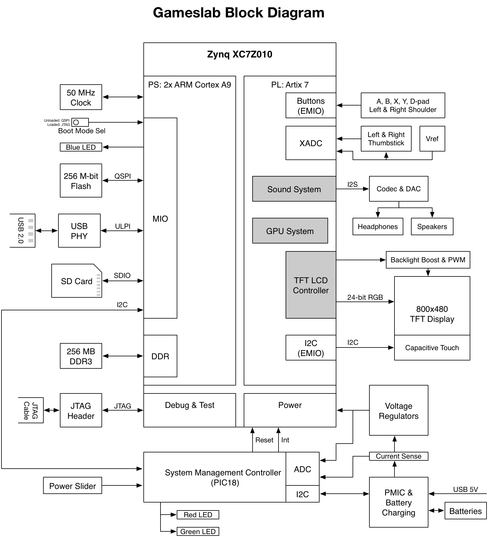 In the Zynq SOC, PS refers to the ARM Cortex A9 sub-system, and PL refers to the programmable logic section. EMIO is a function for passing PS I/O through the PL fabric. Grey blocks will be implemented in programmable logic.
After thinking about what a pain it would be to monitor voltages and currents with the Zynq XADC and do power management with the huge ARM PS with U Boot and Linux, I added a system management controller to the design (SMC). I realized that something had to monitor and control the power-up sequence, and only boot the Zynq when the battery status allows. Doing this with the XADC in the Zynq would require booting the entire processor and PL section, and possibly loading a bitstream–all that just to check the battery voltage. In addition, I wanted to use a momentary slide switch for controlling power, mostly because they feel nice. However, if I hooked this to the Zynq, it’d have to be on some GPIO interrupt, which means the Zynq would boot by default when power is present, power down, and then wait for the switch interrupt. I’d rather keep the whole Zynq powered down when in standby. I don’t plan on my embedded Linux distro taking long to boot.
So, in this revised design, the SMC is a PIC18 microcontroller with its ADC connected to the battery voltage, system voltages, and a system current sense amplifier. It also controls the battery PMIC through an I2C interface. This way, when power is applied, the SMC starts up and monitors the power supplies. If the slide switch is pulled and sufficient battery charge is available, the SMC triggers the Zynq power-up reset. I chose the PIC18 family because I’ve used them on dozens of previous projects, so they’re familiar. However, any 8-bit micro would do.
For the PMIC, I want a chip that will charge with at least 1.5 A, since I want to use three 2500 mAh lithium polymer batteries. I found a couple TI chips that could work, and I’ll post more details when I go through the power system. I also took a look at loads of switching voltage regulators, and I think I’ve decided on all discrete switchers. There are some large chips that integrate 3-6 switching regulators in one, but they all either have the wrong combination of output voltage ranges, currents, or number of regulators. Plus, I want to individually control each supply. This way, the SMC can properly sequence power for the Zynq, and keep the PL shut-down when not necessary. The LEDs on the SMC will indicate charging and power status. Red will mean it’s charging, green will mean the system is on.
I debated whether I should add Wi-fi to the system, using a TI industrial Wi-fi module on an SDIO interface. For example, the TI WL1807MOD is a high-speed completely integrated Wi-fi module. Add antennas, power, and a passive or two, and it does 80 Mbps 802.11n. However, I think for this first revision, network-over-USB will be fine. USB networking will be much simpler to get working in U Boot and Linux.
I will use the XADC for the thumbsticks though! Originally I had them connected to the SMC as well, since I was already using the ADC there. However, The Zynq has the XADC, and it might be interesting to use custom PL hardware to filter the thumbstick input. The buttons also go through the PL pins. These can either pass through the EMIO to the PS GPIO controller, or the custom PL logic can manage them.
Well, I think I pretty much have a plan now. So time to finish fiddling around with my schematics so I can finish this PCB design.